Optex HX-40 Installation Instructions Manual
High mount outdoor detector
Hide thumbs
Also See for HX-40:
- Installation instructions manual (72 pages) ,
- Installation instructions manual (20 pages) ,
- Installation instructions manual (12 pages)
Table of Contents
Advertisement
Quick Links
High Mount
High Mount
Outdoor Detector
Outdoor Detector
HX -40/40AM
HX -40/40AM
By utilising the OPTEX's unique pyro-element,
HX series achieves high reliable detection
performance against false and missed alarms.
HX series provides stable and accurate
detection in outdoor severe environmental
conditions.
•HX-40
: standard model with two PIRs
•HX-40AM
: HX-40 with IR anti-masking
feature
1
INSTALLATION HINTS
Warning
Never repair or modify product
Parallel
Mount the detector so that a majority of traffic flow is across the detection pattern.
CONTENTS
(1) INSTALLATION HINTS
(2) PARTS IDENTIFICATION
(3) KNOCKOUTS
(4) DETECTION AREA SETTING
(5) INSTALLATION
(6) BRACKET INSTALLATION AND ADJUSTMENT
(7) WIRING
(8) FUNCTION SETTING
(9) OPERATION TEST
(10) LED FUNCTIONS
(11) SPECIFICATIONS
Warning
Do not pour water over the
product
Tilt
-1-
INSTALLATION INSTRUCTIONS
Mount securely
2.5 - 3.0 m
(8.3 - 10 ft.)
No.59-1501-2
N219
1
2
2
3
3
4
6
7
9
10
11
Caution
Advertisement
Table of Contents

Related Manuals for Optex HX-40


Summary of Contents for Optex HX-40
- Page 1 HX -40/40AM HX -40/40AM CONTENTS (1) INSTALLATION HINTS (2) PARTS IDENTIFICATION By utilising the OPTEX’s unique pyro-element, HX series achieves high reliable detection (3) KNOCKOUTS performance against false and missed alarms. (4) DETECTION AREA SETTING HX series provides stable and accurate...
-
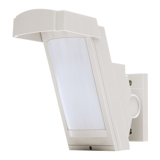
Page 2: Parts Identification
PARTS IDENTIFICATION Bracket base Base Screw (3×10 mm) Terminals Main unit Hood PIR sensor (Don not touch) Anti-masking infrared LED Bracket (HX-40AM only) Shaft cover Screw (4×20 mm) Lock screw (M4×35 mm) Lens LED indicator Cover Area Lock screw masking seal KNOCKOUTS Main unit Bracket... -
Page 3: Detection Area
DETECTION AREA SETTING Detection Area Side view of detection area Top view of detection area (Installation height 3.0 m (1 ft.) ) 12 m (40 ft.) (26.7ft.) (Installation height 2.5 m) 12 m (40 ft.) • Accessory bracket is required when the HX is installed at 2.5m (8.3 ft.) height. -
Page 4: Bracket Installation
Fasten the base to the wall. Put the main unit and lens. BRACKET INSTALLATION AND ADJUSTMENT Using the bracket makes it possible to adjust the unit through 180° degree. In cases where the ground is uneven and therefore not parallel with the base of the unit, it is possible to adjust the unit vertically by ±... - Page 5 Fasten the bracket to the wall. Pass the wire through the base knockout Change the bracket direction according and install the base on the bracket. to whether the Main unit is to face left or right. Wiring sponge pad Open the wiring knockout and up-down Tighten the adjustment screw clockwise.
- Page 6 (8.3 ft.) height installation to maintain the 12m (40 ft.) detection range. NOTE: This setting is available only for the HX is installed vertically to the ground. WIRING Power wires should not exceed the following lengths. HX-40 HX-40AM WIRE GAUGE AWG22 (0.33 mm 160m (520ft)
-
Page 7: Function Setting
4 TROUBLE OUTPUT SELECTOR (8-D) ANTI-MASKING PIR SENSITIVITY SELECTOR (8-E) SENSITIVITY SELECTOR (8-F) Do not touch HX-40 LED ON/OFF Dip switch HX-40AM POSITION FUNCTION The LED lights when someone is detected. (factory default) The LED does not light even if someone is detected NOTE: For the walk test, move more than 1 m (3.3 ft.) away from... -
Page 8: Trouble Output
HX-40 TROUBLE OUTPUT Dip switch HX-40AM Trouble output is used for anti-masking signal. When an object is placed close to the lens surface, for a period of more than 180 seconds, the IR Anti-Masking circuit will activate and generate a trouble signal. -
Page 9: Operation Test
OPERATION TEST Example of adjustment for false alarms If there is a road where people or vehicles can pass in front of the detection area, and can trigger false alarms, adjust the area as follows. Delete the unneccesory detection area (a) using the appropriate masking seal(s) 1 2 or 3. -
Page 10: Led Functions
Configure the area in such a way as to avoid having anything cut across the area. Pasting on example for masking No. 5 and No. 6 Area masking seal LED FUNCTIONS Light Blink HX-40 DETECTOR STATUS LED Indication LED operation Alarm Red light Warm-up period... -
Page 11: Specifications
SPECIFICATIONS HX-40 HX-40 AM Model Passive infrared Detection method PIR Coverage 12 m (40 ft.) 85° wide / 94 zones Distance limit 4 m, 5.5 m, 9 m, 12 m (13 ft, 18 ft, 30 ft, 40 ft.) Detectable speed 0.3 –... - Page 12 Unit:mm (inch) Unit:mm (inch) The HX-40 series is designed to detect movement of an intruder and activate an alarm control panel. Being only a part of a complete system, we cannot accept complete responsibility for any damages or other consequences resulting from an intrusion. Due to our policy of continuous improvement Optex reserves the right to change specification without prior notice.
Need help?
Do you have a question about the HX-40 and is the answer not in the manual?
Questions and answers