
Related Manuals for Retsch Mixer Mill MM 500 nano


Summary of Contents for Retsch Mixer Mill MM 500 nano
- Page 1 Manual Mixer Mill MM 500 nano Translation © Retsch GmbH, 42781 Haan, Retsch-Allee 1-5, Germany | 15.03.2022 Version 0001...
- Page 2 Copyright © Copyright by Retsch GmbH Retsch-Allee 1-5 42781 Haan Germany...
-
Page 3: Table Of Contents
Table of Contents Notes on the manual ..........................7 Disclaimer ............................7 Copyright............................7 Explanation of signs and symbols ..................... 7 Explanations of the Safety Instructions ..................... 8 Safety ..............................9 Intended use of the device......................... 9 Improper use ............................9 Obligations of the operating company ..................... - Page 4 6.7.1 Opening the grinding jar ......................38 6.7.2 Filling the grinding jar ........................39 6.7.3 Closing the grinding jar ........................ 40 Inserting the Grinding Jar ........................ 41 6.8.1 Opening the grinding jar support ....................42 6.8.2 Inserting the grinding jar ......................42 6.8.3 Closing the grinding jar support ....................
- Page 5 10.1 Returning for repair and maintenance ..................... 85 Accessories ............................87 Disposal ..............................88 Index ..............................90...
- Page 6 Notes on the manual...
-
Page 7: Notes On The Manual
You can find further information about your device at https://www.retsch.com on the pages for the specific device concerned. Amendment status: The document amendment 0001 of the "Mixer Mill MM 500 nano" manual has been prepared in accordance with the Directive of Machinery 2006/42/EC. 1.1 Disclaimer Die v orliegende Bedi enungs anleitung w urde mi t größter Sorgfalt erstellt. -
Page 8: Explanations Of The Safety Instructions
Notes on the manual 1.4 Explanations of the Safety Instructions DANGER D1.0000 Risk of fatal injuries Source of danger − Possible consequences if the danger is ignored. • Instructions and information on how to avoid the risk. Fatal or serious injuries may result if the “Danger” sign is disregarded. There is a very high risk of a life-threatening accident or lasting personal injury. -
Page 9: Safety
This manual is therefore directed at persons who work with this device in a comparable environment and who already have experience with similar equipment. The MM 500 nano is a modern, efficient, state-of-the-art product from Retsch GmbH. Its reliability is ensured when used as intended and with knowledge of this technical documentation. -
Page 10: Obligations Of The Operating Company
Safety 2.3 Obligations of the operating company 2.3.1 Provisions The user bears responsibility for ensuring that people working with the device and the corresponding equipment have taken note of and understood all relevant safety regulations. 2.3.2 Personnel • Ensure that only trained personnel are deployed whose training and experience enable them to recognise risks and avoid potential hazards. -
Page 11: Personal Protective Equipment (Ppe)
2.5 Repairs This manual does not contain any repair instructions. For safety reasons, repairs may only be carried out by Retsch GmbH or an authorised representative or by qualified service technicians. In case of repair, please inform… …the Retsch GmbH representative in your country, …your supplier, or... -
Page 12: Preventing Risks During Normal Operation
Safety 2.6 Preventing risks during normal operation The failure to comply with the following safety instructions constitutes improper use and presents a risk to personnel and to operational safety. Transport and installation • Do not carry the device by yourself during transport and installation. •... -
Page 13: Preventing Damage To Equipment
Safety 2.7 Preventing damage to equipment • Protect the device against condensation if large fluctuations in temperature are to be expected (e.g. during air transport. • Do not knock, shake or throw the device during transport and installation. • Comply with conditions at the installation site when installing the device. •... -
Page 14: The
The Mixer Mill MM 500 nano The Mixer Mill MM 500 nano The MM 500 nano from Retsch GmbH is a laboratory device used to prepare samples. The device permits the fast grinding, mixing and homogenisation of soft, medium-hard, fibrous and brittle materials with a particle size of up to 10 mm. -
Page 15: Technical Data
The Mixer Mill MM 500 nano 3.1 Technical data General information Applications For (dry and wet) grinding, mixing, homogenisation, cell disruption, cryogenic grinding Area of application Agriculture, biology, chemicals, plastics, building materials, engineering, electrical engineering, environment, foodstuffs, geology, metallurgy, glass, ceramics, medicine,... -
Page 16: Emissions
The Mixer Mill MM 500 nano 3.2 Emissions CAUTION C.0020 Risk of injury caused by not hearing acoustic signals Loud grinding noise − Loud grinding noise may result in not hearing acoustic warning signals, leading to injuries. • Take the volume of grinding noise into consideration when designing the acoustic signals in the working environment. -
Page 17: Views Of The Device
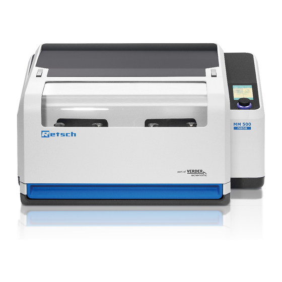
The Mixer Mill MM 500 nano 3.3 Views of the device 3.3.1 Front Fig. 2: Device hood closed Fig. 3: Device hood open t Component Function Device hood Closes the inside of the device. Touchscreen with dial For controlling the device. To select and configure grinding parameters. -
Page 18: View Of The Grinding Jar Support
The Mixer Mill MM 500 nano 3.3.2 View of the grinding jar support Fig. 4: Grinding stations Fig. 5: Grinding jar support Component Function Grinding stations Position of the grinding jar supports to hold the grinding jars. Clamp For mounting the grinding jars. -
Page 19: Back
The Mixer Mill MM 500 nano Direction of rotation of Opens the clamps, thereby enabling the grinding jar to be the locking wheel: removed. open the clamps 3.3.3 Back Fig. 6: Back of the device Component Function USB interface To update the operating software. -
Page 20: Signs On The Device
The Mixer Mill MM 500 nano 3.4 Signs on the device Fig. 7: Signs on the device Sign Meaning Wear hearing protection Safety warning: We recommend that you wear hearing protection when operating the device for a long period of time. -
Page 21: Type Plate Description
The Mixer Mill MM 500 nano 3.5 Type Plate Description Fig. 8: Type plate 1 Device name 2 Year of manufacture 3 Article number 4 Serial number 5 Manufacturer’s address 6 CE mark 7 Disposal sign 8 Barcode 9 Power version... -
Page 22: Packaging, Transport And Installation
N4.0014 Complaints Incomplete delivery or transport damage − The forwarding agent and Retsch GmbH must be notified immediately in the event of transport damage. It is otherwise possible that subsequent complaints will not be recognised. • Please check the delivery on receipt of the device for its completeness and intactness. -
Page 23: Temperature Fluctuations And Condensation
Packaging, Transport and Installation 4.3 Temperature Fluctuations and Condensation NOTICE N5.0016 Damaged components due to condensation Temperature fluctuations − The device may be exposed to substantial fluctuations in temperature during transport. The ensuing condensation can damage electronic components. • Wait until the device has acclimatised before putting it into service. Temporary storage: Also in case of an interim storage the device must be stored dry and within the specified ambient temperature range. -
Page 24: Removing The Transportation Lock
Packaging, Transport and Installation For ambient temperatures U between 31 °C and 40 °C, the maximum relative humidity value L = –(U – 55) / 0.3: linearly decreases according to L Ambient temperature Max. rel. humidity ≤ 31 °C 80 % 33 °C 73.3 % 35 °C... - Page 25 Packaging, Transport and Installation Fig. 9: Unscrewing the transport lock Component Screw Transport lock Remove the transport lock and transport the device as follows: Unscrew and remove the six screws (S), three on each side of the device. The transport lock is simultaneously also a transport aid . ...
-
Page 26: Removing The Transportation Aid
Packaging, Transport and Installation Component Transport aid The transport aid (TH) can also be used to lift the device by crane. Transport the device by crane as follows: Attach lifting belts to both of the transport aids (TH). Transport the device by crane to the application site. NOTICE The housing may be damaged if the lifting belts are too short. -
Page 27: First Commissioning
First Commissioning First Commissioning 5.1 Electrical Connection WARNING W4.0015 Risk to life caused by an electric shock Connection to socket without a protective earth conductor − Connecting the device to sockets without a protective earth conductor can lead to life-threatening injuries caused by an electric shock. •... -
Page 28: Connecting The Device To The Power Supply
First Commissioning 5.2 Connecting the device to the power supply Fig. 12: Connecting to the power supply Component Appliance socket Type plate Connect the device to the power supply as described below: Compare the voltage and frequency on the type plate (N) of the device to the values on site. -
Page 29: Operating The Device
Operating the Device Operating the Device WARNING W6.0002 Danger to life through electric shock Damaged power cable − Operating the device with a damaged power cable or plug can lead to life- threatening injuries caused by an electric shock. • Before operating the device, check the power cable and plug for damage. -
Page 30: Switching The Device On/Off
Operating the Device 6.1 Switching the device on/off Fig. 13: Main switch Fig. 14: Front of the device with touchscreen Component Main switch Device hood Touchscreen with dial Switch the device on as follows: Switch the device on by the main switch (I) on the back of the device. ... -
Page 31: Opening And Closing Of The Device
Operating the Device Open the device hood (H) by hand and then close it again. The device is then ready for use. Switch the device off as follows: Switch the device off by the main switch (I) on the back of the device when no grinding process is running. -
Page 32: Specifications Regarding Grinding Balls And Grinding Jars
Operating the Device Component Device hood Open the device as follows: Lift the device hood (H) by hand and open it completely. The device hood is fitted with cushioning. This cushioning ensures that the device hood does not open in an uncontrolled manner. The cushioning on the device takes effect as from an opening angle of approx. -
Page 33: View Of Grinding Jars
Operating the Device 6.4 View of grinding jars Fig. 17: Grinding jars Component Function Grinding jar cover Closes the grinding chamber on the grinding jar. Sealing ring For sealing between the grinding jar cover and grinding jar. May be replaced if worn. Grinding chamber To accommodate the grinding balls and material. -
Page 34: Grinding Jar Identification
Operating the Device ÖH ÖR ÖS Opening aid Fig. 18: Component Function ÖH Opening aid The clamping screws on the grinding jar cover are tightened using the supplied opening aid . The opening aid can additionally be used to unscrew the clamping screws on the grinding jar and the locking wheels on the grinding jar support. -
Page 35: Recommended Grinding Jar Filling
Operating the Device 6.5.4 Recommended Grinding Jar Filling In addition to device settings, the fill level of the grinding jars is crucial for the success of grinding in the Mixer Mill. When grinding bulk materials, a grinding jar filling should consist roughly of one third sample material and one third ball volume. -
Page 36: Special Grinding Methods
Indirect embrittlement with liquid nitrogen ( - 196 °C) improves the fracture behaviour of thermoplastics, rubber products, greasy foodstuffs, pharmaceuticals etc. For cryogenic grinding, Retsch GmbH offers the Cryo Kit (Order Number: 22.354.0003) for cooling the grinding jars with liquid nitrogen. -
Page 37: Wet Grinding With Highly Flammable Materials
Operating the Device 6.6.2 Wet Grinding with Highly Flammable Materials Wet grinding using highly flammable materials is permitted with this device if certain precautionary measures are complied with. When using highly flammable materials such as hexane, isopropyl, ethanol, benzine etc. as a grinding aid , the inside of the grinding jars should be classed as Zone 0, i.e. -
Page 38: Opening The Grinding Jar
Operating the Device 6.7.1 Opening the grinding jar CAUTION C9.0024 Risks of burns and scalding Hot grinding jar and/or sample material − The sample material and grinding jar can get very hot during the grinding process. • After grinding, always wear protective gloves when handling the grinding jar. -
Page 39: Filling The Grinding Jar
Operating the Device Grinding jar cover Grinding chamber Open the grinding jar as follows: Loosen both clamping screws (SP) on the grinding jar cover (MD) and unscrew evenly until the grinding jar cover (MD) can be lifted off without becoming misaligned. ... -
Page 40: Closing The Grinding Jar
Operating the Device 6.7.3 Closing the grinding jar Fig. 21: Closing the grinding jar Component Grinding jar cover Guide bolts Grinding chamber Clamping screws Close the grinding jar as follows: Place the grinding jar cover (MD) suitably onto the two guide bolts (FB) of the grinding jar and close the grinding chamber (MR). -
Page 41: Inserting The Grinding Jar
Operating the Device Tightening the clamping screws by hand is not sufficient to completely seal the grinding jar. The clamping screws may break off, however, if too much force is exerted with the opening aid. 6.8 Inserting the Grinding Jar NOTICE N16.0067 Strong vibrations and loud noise... -
Page 42: Opening The Grinding Jar Support
Operating the Device 6.8.1 Opening the grinding jar support Fig. 22: Opening the grinding jar support Component Grinding jar support Clamp Locking wheel Open the grinding jar support as follows: Twist the locking wheel (SR) on the grinding jar support (MH) in an anticlockwise direction to open the clamp (KB). - Page 43 Operating the Device Component Grinding jar Grinding jar support Clamping wedge (Grinding jar support) Grinding jar guide Insert the grinding jar in the grinding jar support as follows: Insert the grinding jar (MB) correctly into the grinding jar support (MH). Ensure that the grinding jar guide (MF) is positioned correctly in the grinding jar support (MH).
- Page 44 Operating the Device The clamping wedges on the grinding jar support lie above those on the grinding jar. The clamps can therefore be closed correctly. Fig. 25: Grinding jar flush with grinding jar support NOTICE Both grinding stations must always be loaded. If only one grinding jar is required, the second grinding jar must be inserted empty (without grinding balls, without sample material) as a counterweight.
-
Page 45: Closing The Grinding Jar Support
Operating the Device 6.8.3 Closing the grinding jar support Fig. 27: Clamping the grinding jar Fig. 28: Device with loaded grinding stations Component Locking wheel... -
Page 46: Grinding Process
Operating the Device Grinding jar support Clamp Grinding jar Clamping wedges (Grinding jar and grinding jar support) Close the grinding jar support as follows: Turn the locking wheel (SR) on the grinding jar support (MH) clockwise to close the clamp (KB) and to firmly clamp the grinding jar (MB). -
Page 47: Starting The Grinding Process
Operating the Device 6.9.1 Starting the grinding process Fig. 29: Starting the grinding process Component Device hood Touchscreen Dial Start the grinding process as follows: Close the device hood (H) by hand. Configure the parameters for grinding on the touchscreen (T) and using the dial (DK). ... - Page 48 Operating the Device • Allow grinding jars to cool down to room temperature before opening them. NOTICE N19.0007 Handling foodstuffs, pharmaceuticals and cosmetic products Products processed − Foodstuffs, pharmaceuticals and cosmetic products that have been processed on the device may no longer be eaten, used or put into circulation,.
- Page 49 Operating the Device Fig. 32: Opening the grinding jar for emptying Component Device hood Locking wheel Grinding jar support ÖH Opening aid Grinding jar Clamping screws Grinding jar cover Grinding chamber Remove the sample material as follows: Wait for the end of the grinding process. ...
- Page 50 Operating the Device Open the clamping screws (SP) on the grinding jar (MB) using the appropriate side of the opening aid (ÖH). Lift the grinding jar cover (MD) off. Remove the sample material from the grinding chamber (MR).
-
Page 51: Device Control
Device control Device control The device is controlled using the touchscreen in combination with the dial . These control elements are used to configure parameter settings for grinding and to start, pause and end the grinding process. Parameters for recurring grinding processes are configured, stored and selected as necessary in the program and cycle mode. -
Page 52: Menu Interface On The Touchscreen
Device control 7.1 Menu interface on the touchscreen The menu surface of the touch display is divided into the following areas: Fig. 34: Menu surface of the touch display Area Function The following menu views can be called up via the navigation Navigation area area: •... -
Page 53: Function Elements
Device control Indicator for the position of the menu. Scroll bar The device is controlled directly with the functional elements Control in this area. • Start, pause and cancel the grinding process • Select, edit, save, delete and start the selected program •... - Page 54 Device control Element Description Function Cycle programme Access to cycle programme mode. mode Edit programme and This can be used to create new programmes and cycle programme cycle programmes and edit saved programmes and cycle programmes. Delete programme/ Deletes a created programme or a cycle cycle programme programme.
- Page 55 Device control Remote Coupling the device with a mobile device. Beeper (on/off) Setting the beeper (on/off) Brightness Setting the display brightness. Calendar Setting the date and time. Software version Display of the installed software. Running time Display of the previous running time. Serial number Display of the device serial number.
-
Page 56: Menu Navigation
Device control 7.3 Menu navigation Switch the device on by the main switch. ➔ Touchscreen is activated and the dial lights up in blue. ➔ Prompt to open and close the device hood is displayed on the touchscreen. Open and close the device hood. ➔... -
Page 57: Main Menu
Device control 7.4 Main menu Additional menu views can be called up via the Main menu. Parameters for the grinding process can be configured and the grinding can also be started. N1.1 N3.1 N2.1 P2.1 P1.1 S1.1 Fig. 36: Main menu (after being switched on with closed cover) P1.1 P2.1 S3.1... - Page 58 Device control P1.1 P2.1 P2.2 S2.1 S3.2 Fig. 38: Menu view during the grinding process P4.1 Fig. 39: Menu view after successfully completed grinding process...
- Page 59 Device control Element Function N1.1 System settings Call up system settings N2.1 Program mode Access to program mode N3.1 Cycle program mode Access to cycle program mode Acoustic signals on / off The sound is switched on when the element is visible. P1.1 Vibration frequency After selection with the touch display, the vibration frequency can be set from 3 - 30 Hz with the dial...
-
Page 60: Controlling The Grinding Process
Device control 7.5 Controlling the grinding process The grinding process can be controlled from the main menu, from the program and the cycle mode using the function elements. Start grinding process Pause grinding process Continue grinding process after a pause Stop grinding process 7.6 Starting the grinding process ... -
Page 61: Program Mode
Device control 7.9 Program mode Press the button (N2.1) in the Main menu to switch to the Program mode. The display changes to the current program. Individual programs can be selected, edited, saved, deleted and started in the Program mode. If sample materials are frequently ground with the same parameters, these parameters can be stored in program memory locations and called up as Standard Operating Procedures (SOP), whenever required. - Page 62 Device control N1.3 P2.1 P1.1 P2.2 S2.1 S3.2 Fig. 41: Program mode after starting the grinding process Element Function N1.2 Main menu Opens the Main menu N1.3 Program mode Access to program mode N3.2 Gallery view Opens the gallery view of the programs or the available program memory locations Program number Number of the selected program...
-
Page 63: Select A Program
Device control 7.9.1 Select a Program Programs with preset parameters for the grinding process can be selected in the Program mode. In order to select a program, press the button (N2.1) in the Main menu. The respective program number is displayed next to the symbol (P1N). - Page 64 Device control N3.2 Fig. 43: Program view Alternatively, you can use the (N3.2) button to switch to the gallery view. Now, four programs are always displayed with the set parameters. N1.2 Fig. 44: Gallery view...
- Page 65 Device control Swipe across the display to switch between program group 1 to 4, 5 to 8 and 9 to 12. The scroll bar (B) gives you a visual overview of your position within the gallery view. To activate a program, tap the desired program section. Element Function N1.2 Main menu...
-
Page 66: Edit A Program
Device control 7.9.2 Edit a Program Open the program editor in the Program mode by pressing the button (S2.2). A program can be created, edited, saved and deleted in the program editor. N2.2 N1.2 S2.3 S1.2 Fig. 45: Program editor Element Funktion N1.2 Main menu... -
Page 67: Save A Programme
Device control 7.9.3 Save a Programme Proceed as follows to save the configured parameters in a program preset: Press to save the configured parameters in the selected program preset. 7.9.4 Delete a Programme To delete all parameters of a programme, tap on the button (S1.2). - Page 68 Device control N1.2 S3.1 S2.2 Fig 46: Cycle program mode S2.1 S3.2 Fig. 47: Cycle program mode after starting the grinding process...
- Page 69 Device control Element Function N1.2 Main menu Opens the Main menu Number of the cycle Displays the number of the current cycle program program Parameter sets (A/B) A cycle program is divided into parameter sets A and B. Parameter settings Displays the parameters of the active cycle program (vibration frequency or grinding time) Repetitions of the cycle...
-
Page 70: Selecting The Cycle
Device control 7.10.1 Selecting the cycle In the cycle program mode, cycle programs with preset parameters for the grinding process can be selected. In order to select a cycle program, press the button in the Main menu. The respective number of the cycle program is displayed next to the symbol N1.2 S3.1 S2.2... -
Page 71: Editing The Cycle
Device control Press the symbol to start the selected cycle program and the grinding process. Press the symbol in order to exit the cycle program mode and return to the Main menu. 7.10.2 Editing the cycle Cycle programs can be created, edited, saved and deleted in the editor of the cycle program. N2.2 N1.2 S1.2... -
Page 72: Saving The Cycle
Device control The total duration of a cycle program must not exceed 99 hours. A total duration of more than 99 hours cannot be saved and is marked in red. The process can be cancelled by pressing the button All settings made will then be discarded. -
Page 73: System Settings
Device control 7.11 System settings The system settings can be accessed from the main menu. Press the symbol Swipe from right to left or left to right to access the three different system settings windows. Then press the desired section to view or configure settings. Fig. - Page 74 Device control Fig. 51: System settings Page 2 SE10 Fig. 52: System settings Page 3...
-
Page 75: Myretsch
Software update of the device via USB data carrier 7.11.1 MyRetsch This section gives access to the Retsch GmbH web portal via a QR code. This may be read using a smartphone with the appropriate software and an internet connection. Additional information such as tips and tricks and an application database can be accessed. - Page 76 Device control Image 53: MyRetsch QR code to access the web portal: Image 54: QR code...
-
Page 77: Remote
Device control 7.11.2 Remote By selecting the “Remote” section, the device can be controlled via a smartphone, tablet or PC. Tap on the “Remote” section to establish a connection. Fig. 55: Remote Remote device control is only possible after the optional Retschbox WLAN module has been installed and set up. -
Page 78: Signalling Device
Device control Fig. 56: Remote The display shows the information • vibration frequency, • grinding time For more information on connecting the device to the WLAN module and controlling the device via remote, please refer to the separate Retschbox operating instructions. 7.11.3 Signalling device The signalling device on the device can be switched on or off using this section. -
Page 79: Software Version
The service environment can be accessed using this section. The service environment can only be accessed by service technicians who have been authorised by Retsch GmbH. If the service environment is selected, the USB interface is activated and "On" displayed beneath the symbol. -
Page 80: Error Messages And Information Notes
Turn off the main switch and wait 30 sec. before turning on the device again. • If the error persists, please contact the service of Retsch GmbH. Error – Ventilation The fan is blocked and does not start. • Check whether the fan is blocked by a foreign object. - Page 81 Turn off the main switch and wait 30 sec. before switching the device on again. • If the error persists, please contact the service of Retsch GmbH. Error – Speed sensor The set rotation speed and the actual rotation speed of the drive differ from one another.
-
Page 82: Information Notes
Error Messages and Information Notes 8.2 Information Notes Notices inform the user on specific device or programme processes. The operation of the device or programme may be interrupted briefly, but there is no fault. The information notice must be acknowledged by the user to continue the process. Information notices provide additional information for the user as an aid, but do not represent any device or programme errors. -
Page 83: Servicing
Improper repairs − Unauthorised and improper repairs can cause injuries. • Repairs to the device may only be carried out by the Retsch GmbH , an authorised representative or by qualified service technicians. • Do not carry out any unauthorised or improper repairs to the device! 9.1 Cleaning... -
Page 84: Cleaning The Outside Of The Device
Servicing 9.1.1 Cleaning the outside of the device Clean the housing of the device with a damp cloth and, if necessary, a household cleaning agent. Make sure that no water or cleaning agent gets into the interior of the device. ... -
Page 85: Maintenance
Improper repairs − Unauthorised and improper repairs can cause injuries. • Repairs to the device may only be carried out by the Retsch GmbH , an authorised representative or by qualified service technicians. • Do not carry out any unauthorised or improper repairs to the device! The grinding tools may become worn, depending on the frequency of the grinding operation and the sample material. - Page 86 When returning a device, attach the return form to the outside of the packaging. In order to eliminate any health risk to the service technicians, Retsch GmbH reserves the right to refuse the acceptance and to return the respective delivery at the expense of the sender.
-
Page 87: Accessories
Information about parts subject to wear and tear and small accessories can be found in the complete catalogue for the Retsch GmbH, likewise available on the website. In the event of questions about spare parts, please contact the representative for Retsch GmbH in your country or contact Retsch GmbH directly. -
Page 88: Disposal
Disposal 12 Disposal In the case of a disposal, the respective statutory requirements must be observed. In the following, information on the disposal of electrical and electronic devices in the European Community are given. Within the European Community the disposal of electrically operated devices is regulated by national provisions that are based on the EU Directive 2012/19/EU on Waste Electrical and Electronic Equipment (WEEE). - Page 89 Disposal...
-
Page 90: Index
13 Index Device close ............... 31 Accessories ............90 open..............31 Ambient temperature ........23, 24 Device control ..........53, 82 Amendment status ..........7 device hood ............49 Amount of energy ..........35 Device hood ..... 17, 18, 30, 31, 32, 48, 49, 51 Appliance socket .......... - Page 91 Frequency ............27 Lifting the device .......... 25, 26 Front..............17 Loading the grinding stations ......45 Front of the device with touchscreen ....30 Loading the grinding stations ......45 Function elements ........53, 55 Loading the grinding stations ......46 Fuse rating ............
- Page 92 Repair instructions ..........11 Temperature range ..........23 Repetitions of the cycle program ....71, 73 Temporary storage ..........23 Retsch APP ............15 The MM 500 ............14 Retschbox ............. 19, 20 Time ............. 78, 81 Return ..............22 Total duration of the cycle program ..
- Page 93 Views of the device ..........17 Weight ............16, 25 Voltage ..............27 Wet grinding ............38 Volume decrease during grinding ....... 35 with highly flammable materials ..... 38 Volume increase during grinding ......35 Workplace-related emission value ....16, 17 Warning Year of manufacture ..........
- Page 95 Copyright © Copyright by Retsch GmbH Retsch-Allee 1-5 42781 Haan Germany...
Need help?
Do you have a question about the Mixer Mill MM 500 nano and is the answer not in the manual?
Questions and answers