
Related Manuals for Retsch MM 500 Vario


Summary of Contents for Retsch MM 500 Vario
- Page 1 Manual Mixer Mill MM 500 Vario Translation © Retsch GmbH, 42781 Haan, Retsch-Allee 1-5, Germany | 04.03.2020 Version 0001...
- Page 2 Copyright © Copyright by Retsch GmbH Retsch-Allee 1-5 42781 Haan Germany...
-
Page 3: Table Of Contents
Preventing risks during normal operation ..................14 Preventing damage to equipment ....................15 Confirmation Form for the Managing Operator................15 The Mixer Mill MM 500 Vario ....................... 17 Technical data ..........................18 Emissions............................18 Views of the device .......................... 20 3.3.1... - Page 4 6.5.2 Filling the grinding jar ........................43 6.5.3 Closing the grinding jar ........................ 43 Inserting the Grinding Jar ........................ 44 6.6.1 Opening the grinding jar support ....................45 6.6.2 Inserting the grinding jar ......................45 Grinding process ..........................46 6.7.1 Starting the grinding process .......................
- Page 5 Index ..............................82...
- Page 6 Notes on the manual...
-
Page 7: Notes On The Manual
You can find further information about your device at http://www.retsch.com on the pages for the specific device concerned. Amendment status: The document amendment 0001 of the "Mixer Mill MM 500 Vario" manual has been prepared in accordance with the Machinery Directive 2006/42/EC. 1.1 Disclaimer This manual has been prepared with great care. -
Page 8: Explanation Of Signs And Symbols
Notes on the manual 1.3 Explanation of signs and symbols The following signs and symbols are used in this manual: Signs and symbols Meaning Indicates a recommendation and/or important information. Bold type Indicates an important term. • List of equivalent points. <... - Page 9 Notes on the manual NOTICE N1.0000 Type of damage to property Source of the damage to property − Possible consequences if the information is ignored. • Instructions and information on how to avoid the damage to property. Damage to property may result if the information is disregarded. The signal word NOTICE additionally used in the running text or in instructions.
-
Page 10: Safety
The MM 500 Vario is designed for the crushing, grinding, mixing and homogenisation of wet and dry soft, medium-hard, fibrous and brittle materials with a particle size of up to 10 mm. As a laboratory machine, the MM 500 Vario may only be used to prepare samples and not as a production machine. -
Page 11: Obligations Of The Operating Company
Safety 2.3 Obligations of the operating company 2.3.1 Provisions The user bears responsibility for ensuring that people working with the device and the corresponding equipment have taken note of and understood all relevant safety regulations. 2.3.2 Personnel • Ensure that only trained personnel are deployed whose training and experience enable them to recognise risks and avoid potential hazards. -
Page 12: Qualification Of Personnel
Safety 2.3.4 Qualification of personnel Work/operating phase Qualification Transport Qualified employee who has been trained in Installation the safe use of the device. Commissioning Operation Controlling Servicing Disposal Work on the electrical equipment on the Electrician who, on the basis of his/her device training, knowledge and experience is able to evaluate the work assigned and... -
Page 13: Protective Equipment
Hood lock The MM 500 Vario is equipped with an automatic hood lock . Once a grinding process has started, a magnetic clamp firmly closes the hood of the device. If the hood is nevertheless opened during a grinding process, the process is interrupted and the device comes to an immediate halt. -
Page 14: Preventing Risks During Normal Operation
Safety 2.6 Preventing risks during normal operation The failure to comply with the following safety instructions constitutes improper use and presents a risk to personnel and to operational safety. Transport and installation • Do not carry the device by yourself during transport and installation. •... -
Page 15: Preventing Damage To Equipment
Safety 2.7 Preventing damage to equipment • Protect the device against condensation if large fluctuations in temperature are to be expected (e.g. during air transport. • Do not knock, shake or throw the device during transport and installation. • Comply with conditions at the installation site when installing the device. •... - Page 16 Safety The managing operator should for legal protection have the user confirm the instruction about the operation of the device. I have read and taken note of the contents of all chapters in this manual as well as all safety instructions and warnings. User Surname, first name (block letters) Position in the company...
-
Page 17: The Mixer Mill Mm 500 Vario
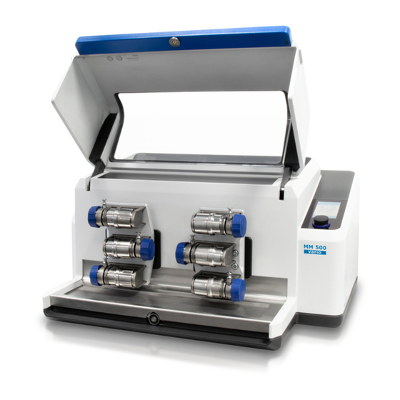
The device permits the fast grinding, mixing and homogenisation of soft, medium-hard, fibrous and brittle materials with a particle size of up to 10 mm. Due to the effective grinding process in a closed system, the MM 500 Vario guarantees gentle preparation of samples ready for analysis in a very short time. -
Page 18: Technical Data
The Mixer Mill MM 500 Vario 3.1 Technical data General information Applications For (dry and wet) grinding, mixing, homogenisation, cell disruption, cryogenic grinding Area of application Agriculture, biology, chemicals, plastics, building materials, engineering, electrical engineering, environment, foodstuffs, geology, metallurgy, glass, ceramics, medicine,... - Page 19 The Mixer Mill MM 500 Vario Risk of injury caused by not hearing acoustic signals Loud grinding noise − Loud grinding noise may result in not hearing acoustic warning signals, leading to injuries. • Take the volume of grinding noise into consideration when designing the acoustic signals in the working environment.
-
Page 20: Views Of The Device
The Mixer Mill MM 500 Vario Example 2 Receptacle 6 steel grinding jars (50 ml) Grinding component 1 steel balls each (25 mm) Feed material Glass breakage Feed quantity 20 g Speed 30 Hz / 35 Hz Under these operating conditions, the workplace-related equivalent continuous sound level l at 30 Hz Leq = 84.2 dB (A) / max. -
Page 21: View Of The Grinding Jar Support
The Mixer Mill MM 500 Vario Component Function Device hood Closes the inside of the device. Touchscreen with dial For controlling the device. To select and configure grinding parameters. Magnetic clamps To keep the device hood closed while the device is being operated. -
Page 22: Back
The Mixer Mill MM 500 Vario Clamp For mounting the grinding jars. Locking wheel To tighten or loosen the grinding jars in the grinding jar support. Centering To tighten or loosen the grinding jar in the grinding jar holder. Locking pin Prevents the grinding jar lock from opening 3.3.3 Back... -
Page 23: Opening Aid
The Mixer Mill MM 500 Vario 3.4 Opening aid Two opening aids are included with delivery of the MM 500 Vario. Use the opening aids to close the grinding jars to ensure that the grinding jars are tightly closed. -
Page 24: Signs On The Device
The Mixer Mill MM 500 Vario 3.5 Signs on the device Fig. 9: Signs on the device Sign Meaning Wear hearing protection Safety warning: We recommend that you wear hearing protection when operating the device for a long period of time. -
Page 25: Type Plate Description
The Mixer Mill MM 500 Vario 3.6 Type Plate Description Fig. 10: Type plate 1 Device name 2 Year of manufacture 3 Article number 4 Serial number 5 Manufacturer’s address 6 CE mark 7 Disposal sign 8 Barcode 9 Power version... -
Page 26: Packaging, Transport And Installation
Packaging, Transport and Installation Packaging, Transport and Installation 4.1 Packaging The packaging has been adapted to the mode of transport. It complies with the generally applicable packaging guidelines. NOTICE N2.0001 Complaint or return Keeping the packaging − Inadequate packaging and insufficient securing of the device can jeopardise the warranty claim in the event of a complaint or return. -
Page 27: Temperature Fluctuations And Condensation
N4.0014 Complaints Incomplete delivery or transport damage − The forwarding agent and Retsch GmbH must be notified immediately in the event of transport damage. It is otherwise possible that subsequent complaints will not be recognised. • Please check the delivery on receipt of the device for its completeness and intactness. - Page 28 − Installation height: max. 2 000 m above sea level The MM 500 Vario must be installed on a stable and solid surface. Vibrations from the device will otherwise be transmitted to the surroundings during the grinding process.
-
Page 29: Removing The Transportation Lock
Packaging, Transport and Installation 4.5 Removing the Transportation Lock WARNING W3.0005 Risk of injury due to the device falling down Lifting the device above head height − The device can fall causing serious injuries when lifted above head height. • Never lift the device above head height! NOTICE N10.0018... - Page 30 Packaging, Transport and Installation Fig. 12: Attach lifting belts Component Transport aid The transport aid (TH) can also be used to lift the device by crane. Transport the device by crane as follows: Attach lifting belts to both of the transport aids (TH). ...
-
Page 31: Removing The Transportation Aid
Packaging, Transport and Installation 4.6 Removing the Transportation Aid Fig. 13: Removing the transport aid Component Transport aid Screw Remove the transport aids as follows: Using a 13 mm open end wrench, loosen and remove the four screws (S), two on each side of the device. -
Page 32: Electrical Connection
Packaging, Transport and Installation 4.7 Electrical Connection WARNING W4.0015 Risk to life caused by an electric shock Connection to socket without a protective earth conductor − Connecting the device to sockets without a protective earth conductor can lead to life-threatening injuries caused by an electric shock. •... -
Page 33: First Commissioning
• Connect the device only to a mains supply matching the values on the type plate. tand hat The MM 500 Vario must be connected to the power supply on site for initial commissioning. Ensure the following before connecting the device to the power supply: •... -
Page 34: Connecting The Device To The Power Supply
First Commissioning 5.1 Connecting the device to the power supply Fig. 14: Connecting to the power supply Component Appliance socket Type plate Connect the device to the power supply as described below: Compare the voltage and frequency on the type plate (N) of the device to the values on site. -
Page 35: Operating The Device
Operating the Device Operating the Device WARNING W7.0002 Danger to life through electric shock Damaged power cable − Operating the device with a damaged power cable or plug can lead to life- threatening injuries caused by an electric shock. • Before operating the device, check the power cable and plug for damage. -
Page 36: Switching The Device On/Off
Operating the Device 6.1 Switching the device on/off Fig. 15: Main switch Fig. 16: Front of the device with touchscreen Component Main switch Device hood Touchscreen with dial Switch the device on as follows: Switch the device on by the main switch (I) on the back of the device. ... -
Page 37: Opening And Closing Of The Device
Operating the Device Switch the device off as follows: Switch the device off by the main switch (I) on the back of the device when no grinding process is running. 6.2 Opening and Closing of the Device CAUTION C8.0008 Risk of pinching and bruising Device hood closing −... -
Page 38: Specifications Regarding Grinding Balls And Grinding Jars
The labelling indicates the size and material of the grinding jar. 6.3.2 Ball Sizes and Speeds A very large amount of energy is applied to the sample material on the MM 500 Vario. This large amount of energy also affects the grinding jars and the grinding balls. -
Page 39: Recommended Maximum Ball Sizes
Operating the Device 6.3.3 Recommended maximum ball sizes Grinding jar size Ball size 1.5 ml 5 mm 5 ml 7 mm 10 ml 12 mm 25 ml 15 mm 35 ml 20 mm 50 ml 25 mm 6.3.4 Recommended Grinding Jar Filling In addition to device settings, the fill level of the grinding jars is crucial for the success of grinding in the Mixer Mill. -
Page 40: Special Grinding Methods
Stainless steel : 145 g 50 ml 8-20 ml 8 mm The MM 500 Vario allows the use of 1.5 ml / 2 ml / 5 ml reaction tubes. Dry grinding Cell disruption of Recommended number of grinding biological cells... -
Page 41: Wet Grinding With Highly Flammable Materials
Indirect embrittlement with liquid nitrogen ( - 196 °C) improves the fracture behaviour of thermoplastics, rubber products, greasy foodstuffs, pharmaceuticals etc. For cryogenic grinding, Retsch GmbH offers the Cryo Kit (Order Number: 22.354.0003) for cooling the grinding jars with liquid nitrogen. -
Page 42: Preparing The Grinding Jar
Operating the Device This approach is regulated in the EU under Articles 118 and 118a of EC Directive 89/391/EEC. Account must be taken of corresponding provisions in other countries outside the EU. 6.5 Preparing the grinding jar NOTICE N15.0011 Wear or damage to the grinding balls and grinding jars Use of different materials −... -
Page 43: Filling The Grinding Jar
Operating the Device Fig. 19: Grinding jars and grinding balls Open the grinding jar as follows: Open the grinding bowl by turning the grinding jar lid. If the grinding jars (SP) cannot be opened, use the opening aids. 6.5.2 Filling the grinding jar Fill the grinding jar as follows: ... -
Page 44: Inserting The Grinding Jar
Operating the Device 6.6 Inserting the Grinding Jar NOTICE N17.0067 Strong vibrations and loud noise Uneven loading − The device can generate particularly strong vibrations and loud noise if loaded unevenly. • Always insert two grinding jars of equal size, even if you only want to grind one sample. -
Page 45: Opening The Grinding Jar Support
Operating the Device 6.6.1 Opening the grinding jar support Fig. 20: Clamping stations Component Locking pin Clamping device Locking wheel Open the clamping device as follows: Pull the locking pin (SB) up out of the groove and turn it 90°. The lock is released. ... -
Page 46: Grinding Process
(without grinding balls, without material) or an adapter must be used as a counterweight. The grinding jar adapters are available as accessories (order number 03.018.0155). Never operate the MM 500 Vario without a grinding bowl or adapter! Operation with grinding jar adapters (shown in blue) Abb. 22: 6.7 Grinding process... -
Page 47: Starting The Grinding Process
Operating the Device CAUTION C11.0006 Risk of injury Sample material that is harmful to health − Sample material that is harmful to health can injure people (illness, contamination). • Use suitable extraction systems with sample material that is harmful to health. •... -
Page 48: Removing The Sample Material
Operating the Device Press on the touchscreen (T) to start the grinding process. The grinding process can only be started by pressing if this symbol is displayed on the touchscreen. is not displayed on the touchscreen, the parameters for grinding have possibly not been completely configured or the device hood has not been closed properly. - Page 49 Operating the Device Component Device hood Locking wheel Clamping device Remove the sample material as follows: Wait for the end of the grinding process. Open the device hood (H). Open the locking wheel (SR) on the grinding jar support (MH) by hand. ...
-
Page 50: Device Control
Parameters for recurring grinding processes are configured, stored and selected as necessary in the program and cycle mode. The system settings for the MM 500 Vario are also selected from the main menu and can be changed where necessary. Fig. 25: Touchscreen and dial... -
Page 51: Menu Interface On The Touchscreen
Device control 7.1 Menu interface on the touchscreen The menu interface on the touchscreen is divided into the following areas: Fig. 26: Menu interface of the touchscreen Area Function Navigation area The following menu views can be selected from the navigation area: •... -
Page 52: Function Elements
Device control 7.2 Function elements Function elements are selected on the touchscreen and configured using the dial. Only the function elements that can currently be selected and configured are displayed and active. The dial lights up in blue when a value that can be altered is selected. Element Description Function... - Page 53 Device control Element Description Function Cycle mode Access to cycle mode. Edit program and cycle New programs and cycles can be created, and saved programs and cycles can be edited here. Delete program/cycle Deletes a created program or a cycle. Save program/cycle Saves a created program or a cycle.
-
Page 54: Menu Navigation
Device control 7.3 Menu navigation Switch the device on by the main switch. ➔ Touchscreen is activated and the dial lights up in blue. ➔ Prompt to open and close the device hood is displayed on the touchscreen. Open and close the device hood. ➔... -
Page 55: Main Menu
Device control 7.4 Main menu Using the main menu, other menu views can be selected, parameters configured for the grinding process and grinding can be started. Fig. 28: Main menu Fig. 29: Menu view after starting the grinding process... -
Page 56: Controlling The Grinding Process
Device control Element Function NB2 System settings To select system settings. NB3 Program mode For access to program mode NB4 Cycle mode For access to cycle mode Vibration frequency Following selection on the touchscreen, the vibration frequency can be set to between 3 and 35 Hz using the dial. -
Page 57: Pausing The Grinding Process
Device control 7.7 Pausing the grinding process Press to pause the grinding. After pausing, the pause sign changes to the continue sign Press to continue the grinding process after a pause. 7.8 Stopping the grinding process The grinding process is stopped automatically once a defined grinding time has expired. Grinding can also be actively stopped by pressing the stop button. - Page 58 Device control Fig. 30: Program mode Fig. 31: Program mode after starting the grinding process Element Function Main menu To return to the main menu. Gallery view Opens the gallery view for programs or the available program presets. Program number Shows the number of the current program.
-
Page 59: Select A Program
Device control Parameter settings Shows the parameters of the active program. Scroll bar Indicates the position of the program. Editor mode Opens the program editor. Program mode Access to program mode. Remaining grinding Displays the remaining grinding time for the grinding time process. -
Page 60: Edit A Program
Device control Swipe the display to switch between the program group 1 to 4, 5 to 8 and 9 to 12. Press the upper third of the desired program section to activate a program. Press to start the selected program and the grinding process. ... -
Page 61: Save A Programme
Device control Press on the parameter you wish to edit. Turn the dial, until the desired value is displayed. Press on the parameter again or select a different parameter to accept the set value 7.9.3 Save a Programme Proceed as follows to save the configured parameters in a program preset: ... -
Page 62: Cycle Mode
Device control 7.10 Cycle mode Press the button in the main menu to switch to cycle mode. The display switches to the current cycle. Cycles can be selected, edited, saved, deleted and started in cycle mode. If sample materials are frequently ground with the same parameters, these parameters can be saved in cycle presets and selected when needed as standard operating procedures (SOP). -
Page 63: Selecting The Cycle
Device control 1 / 3 Fig. 35: Cycle mode after starting the grinding process Element Function Main menu To return to the main menu. Cycle number Displays the number of the current cycle. Parameter settings Displays the parameters of the active cycle. Cycle repeats Displays how often the configured cycle is repeated until the grinding process is finished. -
Page 64: Editing The Cycle
Device control Fig. 36: Selecting the cycle Element Function NB1 Main menu To return to the main menu. Parameter settings Displays the parameters that are configured for the current cycle. Scroll bar Indicates the position of the cycle. GS4 Editor mode Opens the cycle editor. - Page 65 Device control Fig. 37: Cycle editor Element Function NB1 Main menu To return to the main menu. NB6 Cancel Cancels editing of the cycle. Parameter settings Displays the parameter configured for the active cycle. Total duration of the cycle Displays the total duration of the cycle (the total duration consists of the two parameter sets (A/B) and the repeats).
-
Page 66: Saving The Cycle
Device control 7.10.3 Saving the cycle Press to save the set parameters in the selected cycle preset. 7.10.4 Deleting the cycle Press and hold the button for approx. three seconds to delete all parameters in the selected cycle preset. -
Page 67: System Settings
Device control 7.11 System settings You can access the system settings from the main menu. Press Swipe from right to left or from left to right to select the three different system settings windows. Then press on the desired section to view or configure the settings. Fig. - Page 68 Device control Fig. 39: System settings Page 2 SE10 SE11 Fig. 40: System settings Page 3...
- Page 69 Device control Element Function “myRetsch” Shows the QR code on the display. Signalling device (on/off) The signalling device for the device can be switched on or off here. Remote When the function is selected, the device is paired to a smartphone, tablet or PC.
-
Page 70: Myretsch
Device control 7.11.1 myRetsch This section permits access to the Retsch GmbH web portal using a QR code. This can be read using a smartphone that has the relevant software and internet connection. Additional information such as tips and tricks and an application database can then be accessed. -
Page 71: Signalling Device
Device control Fig. 42: Remote You can find further information on connecting the device to the Wi-Fi module and on the remote control of the device in the separate Retschbox manual. 7.11.3 Signalling device The signalling device on the device can be switched on or off using this section. The signalling device generates an acoustic signal as soon as a grinding process finishes. -
Page 72: Brightness
Device control 7.11.4 Brightness Proceed as follows to adjust the brightness level on the touchscreen: Press the section. Turn the dial until the desired level of brightness has been reached on the display. The set value will be accepted as soon as you press this section again or on another section, or as soon as you exit system settings. -
Page 73: Service Environment
The service environment can be accessed using this section. The service environment can only be accessed by service technicians who have been authorised by Retsch GmbH. If the service environment is selected, the USB interface is activated and "On" displayed beneath the symbol. -
Page 74: Information Notes
Error Messages and Information Notes 8.2 Information Notes Notices inform the user on specific device or programme processes. The operation of the device or programme may be interrupted briefly, but there is no fault. The information notice must be acknowledged by the user to continue the process. Information notices provide additional information for the user as an aid, but do not represent any device or programme errors. -
Page 75: Servicing
Improper repairs − Unauthorised and improper repairs can cause injuries. • Repairs to the device may only be carried out by the Retsch GmbH , an authorised representative or by qualified service technicians. • Do not carry out any unauthorised or improper repairs to the device! 9.1 Cleaning... -
Page 76: Cleaning The Outside Of The Device
Servicing 9.1.1 Cleaning the outside of the device Clean the housing of the device with a damp cloth and if necessary, with a household cleaning agent. Pay attention that no water or cleaning agent enters the interior of the device. -
Page 77: Maintenance
Improper repairs − Unauthorised and improper repairs can cause injuries. • Repairs to the device may only be carried out by the Retsch GmbH , an authorised representative or by qualified service technicians. • Do not carry out any unauthorised or improper repairs to the device! The grinding tools may become worn, depending on the frequency of the grinding operation and the sample material. -
Page 78: Returning For Repair And Maintenance
When returning a device, attach the return form to the outside of the packaging. In order to eliminate any health risk to the service technicians, Retsch GmbH reserves the right to refuse the acceptance and to return the respective delivery at the expense of the sender. -
Page 79: Accessories
Information on wear parts and small accessories can be found in the complete catalogue of Retsch GmbH which is likewise available on the website. Please contact the Retsch GmbH agent in your country or Retsch GmbH directly if you have any questions regarding spare parts . -
Page 80: Disposal
Disposal 11 Disposal In the case of a disposal, the respective statutory requirements must be observed. In the following, information on the disposal of electrical and electronic devices in the European Community are given. Within the European Community the disposal of electrically operated devices is regulated by national provisions that are based on the EU Directive 2012/19/EU on Waste Electrical and Electronic Equipment (WEEE). - Page 81 Disposal...
- Page 82 12 Index Date and time ............. 72 Delete ............60, 65 Accessories ............79 Deleting the cycle ..........66 Ambient temperature .......... 28 Device Amendment status ..........7 close ............... 37 Amount of energy ..........38 open..............37 Appliance socket ..........22 Device control ..........
- Page 83 E25 ..............73 H42 ..............74 E26 ..............73 Information notes ......... 73, 74 E41 ..............73 Inserting the grinding jar ........45 E50 ..............73 Installation ............26 E80 ..............73 Installation height ..........28 Error messages ..........73 Installation site Explanations of the safety instructions ....
- Page 84 Temperature fluctuations ........27 Repair ..........13, 75, 77, 78 Temperature range ..........28 Repair instructions ..........13 Temporary storage ..........27 Retsch APP ............18 The MM 500 ............17 Retschbox ............22 Time ............. 69, 72 Return ..............26 Total duration of the cycle ......
- Page 85 Transportation aid Volume decrease during grinding ...... 39 removing ............31 Volume increase during grinding ....... 39 Transportation lock ..........29 removing ............29 Warning Tungsten carbide .......... 40, 76 Information ............9 Type plate ..........24, 25, 32 Warranty claim ........... 26 description ............
- Page 87 Copyright © Copyright by Retsch GmbH Retsch-Allee 1-5 42781 Haan Germany...
Need help?
Do you have a question about the MM 500 Vario and is the answer not in the manual?
Questions and answers