
Subscribe to Our Youtube Channel
Related Manuals for Retsch HM 200


Summary of Contents for Retsch HM 200
- Page 1 Manual Hammer Mill HM 200 Translation © Retsch GmbH, 42781 Haan, Retsch-Allee 1-5, Germany | 06.07.2022 Version 0000...
- Page 2 Copyright © Copyright by Retsch GmbH Retsch-Allee 1-5 42781 Haan Germany...
-
Page 3: Table Of Contents
Putting the device back into service following a fault or unexpected interruption ....... 12 Preventing risks during normal operation ..................12 Avoiding damage to property ......................13 Confirmation Form for the Managing Operator................14 The Hammer Mill HM 200 ........................15 Technical data ..........................16 Emissions............................17 Views of the device .......................... 17 3.3.1... - Page 4 Maintenance ............................45 Cleaning ............................45 7.1.1 Cleaning the outside of the device ....................46 7.1.2 Cleaning of grinding chamber and grinding gear................. 46 Servicing ............................48 7.2.1 Maintenance of pneumatic spring ....................48 7.2.2 Lubricating the device ........................49 7.2.3 Checking the limit switch ......................
- Page 5 Notes on the manual...
-
Page 6: Notes On The Manual
This manual does not contain any repair instructions. Please contact your supplier or contact Retsch GmbH directly if anything is unclear or you have questions about these guidelines or the device, or in the case of any faults or necessary repairs. -
Page 7: Explanation Of Signs And Symbols
Action steps of instructions. ➔ Result of an action step Retsch’s Hammer Mill HM 200 is primarily referred to as a device within the individual sections of these operating instructions. 1.4 Explanations of the Safety Instructions The following warnings in this manual warn of possible risks and damage: DANGER D1.0000... - Page 8 Notes on the manual CAUTION C1.0000 Risk of injuries Source of danger − Possible consequences if the danger is ignored. • Instructions and information on how to avoid the risk. Average to slight injuries may result if the “Caution” sign is disregarded. There is an average or slight risk of an accident or personal injury.
-
Page 9: Safety
2.2 Improper use The HM 200 may only be used as intended. Any purposes used other than those described under the intended use are considered to be contrary. The device is not suitable for processing any sample materials which are able to form explosive air mixtures. -
Page 10: Obligations Of The Operating Company
Safety 2.3 Obligations of the operating company 2.3.1 Provisions The operator is responsible for ensuring that persons working with the device have taken note of and understood all relevant safety regulations. 2.3.2 Personnel • Ensure that only skilled personnel are deployed who, due to their training and experience, are qualified to recognise risks and avoid potential hazards. -
Page 11: Personal Protective Equipment (Ppe)
2.4 Structural modifications and repairs This Manual does not contain any repair instructions. For safety reasons, repairs may only be carried out by Retsch GmbH, an authorised representative or by qualified service technicians. Please notify the following in the event of a repair: •... -
Page 12: Emergencies
Safety 2.6 Emergencies The device can be switched off at any time by using the emergency stop switch on the front of the device. 2.6.1 Switching the device off in an emergency In the event of a malfunction or unexpected interruption of operation, please perform the following steps: ... -
Page 13: Avoiding Damage To Property
Safety • Do not grind explosive and/or flammable substances. • Do not grind substances that may become explosive and/or flammable during the grinding process. • During the operation process, components carrying samples can become very hot. Therefore, wait for the sample to cool down before taking it and wear protective gloves, if necessary. -
Page 14: Confirmation Form For The Managing Operator
Safety 2.9 Confirmation Form for the Managing Operator This manual contains essential instructions for operating and maintaining the device which must be strictly observed. It is essential that they be read by the user and by the qualified staff responsible for the device before the device is commissioned. This manual must be available and accessible at the place of use at all times. -
Page 15: The Hammer Mill Hm 200
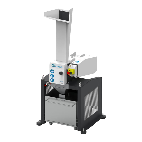
The Hammer Mill HM 200 The Hammer Mill HM 200 The Hammer Mill HM 200 of company Retsch is a laboratory instrument and is used for sample preparation. The device enables the grinding of medium-hard, hard, short-fibred and brittle sample material in dry and slightly moist condition up to a particle size of 100 mm. -
Page 16: Technical Data
The Hammer Mill HM 200 3.1 Technical data Application area Applications Grinding, deagglomeration Application area Agriculture, biology, chemistry, plastics, building materials, engineering, electrical engineering, coal, energy sector environment, food, geology, metallurgy, glass, ceramics, medicine, pharmacy Feed material Hard, medium-hard, brittle, fibrous... -
Page 17: Emissions
The Hammer Mill HM 200 3.2 Emissions CAUTION C.0020 Risk of injury caused by not hearing acoustic signals Loud grinding noise − Loud grinding noise may result in not hearing acoustic warning signals, leading to injuries. • Take the volume of grinding noise into consideration when designing the acoustic signals in the working environment. -
Page 18: Front
The Hammer Mill HM 200 3.3.1 Front Fig. 1: Front view Component Function Batch feed hopper For the portion-wide feeding of sample material into the grinding chamber. Flap Feeding area of the hopper for the portion-wide feeding of material to be grinded. -
Page 19: A View On The Grinding Chamber
The Hammer Mill HM 200 3.3.2 A view on the grinding chamber Fig. 2: Front view of the grinding chamber Component Function Grinding chamber Place for grinding the sample material in the grinding chamber. Hammer Tool for grinding the sample material in the grinding chamber. -
Page 20: Back
The Hammer Mill HM 200 3.3.3 Back Fig. 3: Rear view Component Function Lubrication point Access to the lubrication of the rotor. Damper Securing the folding mechanism to ensure that the device does not collapse. Suction connection Enables the connection of an exhaust system or a vacuum... -
Page 21: Instructions On The Device
The Hammer Mill HM 200 3.4 Instructions on the device Fig. 4: Front view: Safety notes are clearly marked on the device. Fig. 5: Front view with the door opened: Safety notes are clearly marked on the device Fig. 6: Rear view:Safety notes are clearly marked on the device. - Page 22 The Hammer Mill HM 200 Component Function Operating instructions The operating instructions must be read and observed before the device is put into operation. Wearing hearing Safety goggles and hearing protection must be worn when protection and safety operating the device. This PPE prevents eye injuries in...
-
Page 23: Installation Drawing
The Hammer Mill HM 200 3.5 Installation drawing Fig. 7: Set-up drawing –Batch operation... - Page 24 The Hammer Mill HM 200 Fig. 8: Set-up drawing –Continuous operation...
-
Page 25: Type Plate Description
The Hammer Mill HM 200 3.6 Type Plate Description Fig. 9: Type plate 1 Device designation 2 Year of production 3 Part number 4 Serial number 5 Manufacturer’s address 6 CE marking 7 Disposal label 8 Bar code 9 Power version... -
Page 26: Packaging, Transport And Installation
N4.0014 Complaints Incomplete delivery or transport damage − The forwarding agent and Retsch GmbH must be notified immediately in the event of transport damage. It is otherwise possible that subsequent complaints will not be recognised. • Please check the delivery on receipt of the device for its completeness and intactness. -
Page 27: Temperature Fluctuations And Condensation
Packaging, Transport and Installation 4.4 Temperature Fluctuations and Condensation NOTICE N5.0016 Damaged components due to condensation Temperature fluctuations − The device may be exposed to substantial fluctuations in temperature during transport. The ensuing condensation can damage electronic components. • Wait until the device has acclimatised before putting it into service. Temporary storage: Also in case of an interim storage the device must be stored dry and within the specified ambient temperature range. -
Page 28: Removing The Transportation Lock
Packaging, Transport and Installation For ambient temperatures U between 31 °C and 40 °C, the maximum relative humidity value L = –(U – 55) / 0.3: linearly decreases according to L Ambient temperature Max. rel. humidity ≤ 31 °C 80 % 33 °C 73.3 % 35 °C... -
Page 29: Installation Of The Device
Packaging, Transport and Installation Fig. 10: Loosening the transportation lock from the transport pallet 4.7 Installation of the Device WARNING W4.0001 Serious injury Machine tipping over − Bruises and broken bones may result if the machine tips over. • Screw the machine firmly to the base! The device can be transported and set up using either a forklift or a crane. - Page 30 Packaging, Transport and Installation : Base frame with reinforcing rod and mounted rubber feet Fig. 11 The device must be anchored to the ground at its place of installation. Use dowels, 10 mm screws and washers depending on the type and firmness of the ground. If anchoring to the floor is not possible, mount the rubber feet (12) supplied as an alternative.
-
Page 31: First Commissioning
First Commissioning First Commissioning 5.1 Electrical Connection WARNING W5.0015 Risk to life caused by an electric shock Connection to socket without a protective earth conductor − Connecting the device to sockets without a protective earth conductor can lead to life-threatening injuries caused by an electric shock. •... -
Page 32: Establishing The Electrical Connection
First Commissioning tand hat The HM 200 must be connected to the power supply on site for initial commissioning. Ensure the following before connecting the device to the power supply: • The application site complies with the installation requirements; •... -
Page 33: Lubricating The Device When Putting It Into Service For The First Time
First Commissioning 5.3 Lubricating the device when putting it into service for the first time NOTICE: During the initial start-up, the device must be lubricated after eight hours of operation. There are two lubrication points on the device. Please use the supplied grease gun for lubrication. -
Page 34: Operating The Device
Operating the device Operating the device DANGER Danger to life Rotating parts − Intervention during operation may lead to strangulation and bone fractures caused by rotating parts. • Wear work clothes (e.g. no scarves, ties, chains) when operating the device). Secure long hair with a hair net, for example. WARNING W8.0001 Serious injury... - Page 35 Operating the device WARNING W11.0001 Serious bodily injuries Careless use of protective equipment − Improper use of protective equipment may result in hearing damage, eye injury, bruising or broken bones. • Wear hearing protection while operating the machine. • Wear safety shoes, dust mask, gloves and safety goggles when opening the grinding chamber, pulling out the collection container or removing a sieve •...
-
Page 36: Switching The Device On/Off
Operating the device CAUTION C5.0005 Burns Heating of the sample material during grinding − Hot surfaces on the collecting receptacle or the grinding chamber can cause burns. − Hot sample material in the collecting receptacle can cause burns. • Allow the hot sample material to cool down before removing the collecting receptacle and opening the door. -
Page 37: Replacing The Feed Hopper
Operating the device Fig. 14: Emergency stop switch 6.2 Replacing the feed hopper There are two different types of feed hoppers which are available for feeding sample material. The batch feed hopper is suitable for small sample quantities which is equipped with a flap for feeding it in portions, while the feed hopper for continuous operation is suitable for larger sample quantities. -
Page 38: Replacing The Collecting Receptacle
Operating the device 6.3 Replacing the collecting receptacle The sample material which is grinded in the grinding chamber falls into the collecting receptacle. Two different sizes of collecting receptacles are available.The small collecting receptacle (6.1) with a capacity of 10 litres is suitable for small sample quantities. Alternatively, the large collecting receptacle (6.2) with a capacity of 30 litres can be used. -
Page 39: Preparing The Grinding Process
Operating the device Fig. 17: Inserting the large collecting receptacle 6.4 Preparing the grinding process WARNING W14.0003 Serious personal injury Crushing when opening and closing the device − When opening and closing the device, limbs can get trapped and crushed between the tilted upper part and the middle part. -
Page 40: Starting The Grinding Process
Operating the device Slowly swing the grinder gear backwards. Use the handle (3.1). Insert the sieve (16) into the grinding chamber with the bulge facing downwards. Make sure that the lug (16.1) integrated in the sieve points to the front. This lug serves as a removal aid (16.1) later on for the removal of the sieve, should the sieve become jammed. - Page 41 Operating the device CAUTION C8.0026 Danger! Risk of burns and injury due to explosion Mixing of different sample materials − Successive sample preparations of different materials may cause undesirable chemical reactions that can lead to fires or explosions causing injury. •...
- Page 42 Operating the device Fig. 20: Fill in sample material with the batch feed hopper When using the feed hopper for continuous operation: Place small quantities of sample material to be grinded in the feed hopper for continuous operation (2). The sample material falls through the feed hopper into the grinding chamber. ...
-
Page 43: Stopping The Grinding Process
Operating the device 6.6 Stopping the grinding process NOTICE: The device may only be stopped when there is no longer any sample material left to be grinded in the grinding chamber. The hammers could get jammed and thereby damage any mechanical components. - Page 44 Operating the device Fig. 22:Removing the sample material from the collecting vessel.
-
Page 45: Maintenance
Improper repairs − Unauthorised and improper repairs can cause injuries. • Repairs to the device may only be carried out by Retsch GmbH , an authorised representative or by qualified service technicians. • Do not carry out any unauthorised or improper repairs to the device! This chapter contains descriptions on cleaning and servicing the device. -
Page 46: Cleaning The Outside Of The Device
Maintenance 7.1.1 Cleaning the outside of the device Clean the housing of the device with a damp cloth and, if necessary, a household cleaning agent. Make sure that no water or cleaning agent gets into the interior of the device. ... - Page 47 Maintenance CAUTION C16.0006 Risk of injury Sample material that is harmful to health − Sample material that is harmful to health can injure people (illness, contamination). • Use suitable extraction systems with sample material that is harmful to health. • Use suitable personal protective equipment with sample material that is harmful to health.
-
Page 48: Servicing
Risk of injury Improper maintenance − Unauthorised and improper maintenance may cause injuries. • The device may only be serviced by Retsch service technicians or an authorized representative. • The settings for the service range may only be adjusted by Retsch service technicians or an authorised representative. -
Page 49: Lubricating The Device
Maintenance 7.2.2 Lubricating the device NOTICE: During the initial start-up, the device must be lubricated after eight hours of operation. There are two lubrication points on the device. Please use the supplied grease gun for lubrication. Fig. 25:Lubrication points The following quantities of grease are required after a certain interval: Quantity [grams] Interval Operating... -
Page 50: Wear
WARNING In case that a different function is detected other than the sequence described here, the operation of the device must be halted and the service department of the company Retsch GmbH must be contacted. 7.3 Wear In order to ensure the reliability and operational safety of the device, the following components must be checked at least every six months in terms of any signs of wear and tear and, if required, any broken components shall also be replaced. -
Page 51: Rotor Wear
Maintenance 7.3.2 Rotor wear The hammers (14) are attached to the rotor (19), which is driven by the motor, and enable homogeneous specimen grinding. The forces acting during the grinding process cause the rotor to wear and therefore, it may be necessary to replace the rotor at a later point of time. Check the wear and, if necessary, replace the rotor as follows: Open the grinding chamber by opening the door (3) and the tension lock (15). - Page 52 Maintenance Fig. 28: Loosening the tension of the motor 19.1 Fig. 29: Loosening the screw connection of the rotor...
-
Page 53: Returning For Repair And Maintenance
When returning a device, attach the return form to the outside of the packaging. In order to eliminate any health risk to the service technicians, Retsch GmbH reserves the right to refuse the acceptance and to return the respective delivery at the expense of the sender. -
Page 54: Accessories
Information about parts subject to wear and tear and small accessories can be found in the complete catalogue for the Retsch GmbH, likewise available on the website. In the event of questions about spare parts, please contact the representative for Retsch GmbH in your country or contact Retsch GmbH directly. -
Page 55: Disposal
Disposal Disposal In the case of a disposal, the respective statutory requirements must be observed. In the following, information on the disposal of electrical and electronic devices in the European Community are given. Within the European Community the disposal of electrically operated devices is regulated by national provisions that are based on the EU Directive 2012/19/EU on Waste Electrical and Electronic Equipment (WEEE). -
Page 56: Index
Capacity .............. 25 CE marking ............25 Circuit breaker ............ 31 Hammer ............. 19 Clamping lock ............. 19 Hammer mill HM 200 ......... 15 Cleaning .............. 45 Hearing damage ..........17 Cleaning of grinding chamber and grinding gear46 Humidity ............. 28 Cleaning the outside of the device ..... - Page 57 Maximum grain size ..........16 Safety notes on the device ........ 21 Maximum hardness of the feed ......16 Sample material Maximum relative humidity ......... 27 heated ............36 Serial number ............. 25 Service address ..........11 Noise characteristics ........... 17 Servicing ............
- Page 60 Copyright © Copyright by Retsch GmbH Retsch-Allee 1-5 42781 Haan Germany...
Need help?
Do you have a question about the HM 200 and is the answer not in the manual?
Questions and answers