
Related Manuals for Retsch Mixer Mill MM 500 control


Summary of Contents for Retsch Mixer Mill MM 500 control
- Page 1 Manual Mixer Mill MM 500 control Translation © Retsch GmbH, 42781 Haan, Retsch-Allee 1-5, Germany | 31.08.2021 Version 0001...
- Page 2 Copyright © Copyright by Retsch GmbH Retsch-Allee 1-5 42781 Haan Germany...
-
Page 3: Table Of Contents
Preventing risks during normal operation ..................12 Preventing damage to equipment ....................13 Confirmation Form for the Managing Operator................13 The Mixer Mill MM 500 control ......................15 Technical data ..........................17 Emissions............................19 Views of the device .......................... 21 3.3.1... - Page 4 Specifications regarding grinding balls and grinding jars ..............55 View of grinding jars ........................56 Opening aid............................57 6.5.1 Grinding Jar Identification ......................58 6.5.2 Ball Sizes and Speeds ......................... 58 6.5.3 Recommended maximum ball sizes .................... 58 6.5.4 Recommended Grinding Jar Filling ..................... 58 Safety instructions on the handling of liquid nitrogen ..............
- Page 5 7.11.4 Delete a Programme ........................ 96 7.12 Cycle mode ............................96 7.12.1 Selecting the cycle ........................98 7.12.2 Editing the cycle ........................99 7.12.3 Saving the cycle ........................101 7.12.4 Deleting the cycle ........................101 7.13 System settings ..........................101 7.13.1 myRetsch ..........................
- Page 6 Notes on the manual...
-
Page 7: Notes On The Manual
This manual does not contain any repair instructions. Please contact your supplier or contact Retsch GmbH directly if anything is unclear or you have questions about these guidelines or the device, or in the case of any faults or necessary repairs. -
Page 8: Explanations Of The Safety Instructions
Notes on the manual 1.4 Explanations of the Safety Instructions DANGER D1.0000 Risk of fatal injuries Source of danger − Possible consequences if the danger is ignored. • Instructions and information on how to avoid the risk. Fatal or serious injuries may result if the “Danger” sign is disregarded. There is a very high risk of a life-threatening accident or lasting personal injury. -
Page 9: Safety
This manual is therefore directed at persons who work with this device in a comparable environment and who already have experience with similar equipment. The MM 500 control is a modern, efficient, state-of-the-art product from Retsch GmbH. Its reliability is ensured when used as intended and with knowledge of this technical documentation. -
Page 10: Obligations Of The Operating Company
Safety 2.3 Obligations of the operating company 2.3.1 Provisions The user bears responsibility for ensuring that people working with the device and the corresponding equipment have taken note of and understood all relevant safety regulations. 2.3.2 Personnel • Ensure that only trained personnel are deployed whose training and experience enable them to recognise risks and avoid potential hazards. -
Page 11: Personal Protective Equipment (Ppe)
2.5 Repairs This manual does not contain any repair instructions. For safety reasons, repairs may only be carried out by Retsch GmbH or an authorised representative or by qualified service technicians. In case of repair, please inform… …the Retsch GmbH representative in your country, …your supplier, or... -
Page 12: Preventing Risks During Normal Operation
Safety Service address: 2.6 Preventing risks during normal operation The failure to comply with the following safety instructions constitutes improper use and presents a risk to personnel and to operational safety. Transport and installation • Do not carry the device by yourself during transport and installation. •... -
Page 13: Preventing Damage To Equipment
Safety • Under no circumstances fill liquid nitrogen or dry ice into the grinding jar and then close the jar. The high pressure that arises in the jar would burst the grinding jar open. Servicing and repair • Before servicing, switch the device off at the main switch. •... - Page 14 Safety The managing operator should for legal protection have the user confirm the instruction about the operation of the device. I have read and taken note of the contents of all chapters in this manual as well as all safety instructions and warnings. User Surname, first name (block letters) Position in the company...
-
Page 15: The Mixer Mill Mm 500 Control
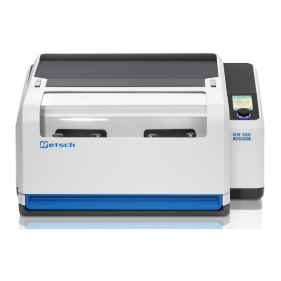
The Mixer Mill MM 500 control The Mixer Mill MM 500 control The MM 500 control is a powerful ball mill which can be used for dry grinding, wet grinding and cryogenic grinding with a frequency of up to 30 Hz. It is the first ball mill on the market that allows controlling and regulating the temperature of the grinding process. - Page 16 The Mixer Mill MM 500 control Fig. 2: Overview of cooling options Component Function MM 500 control - Set The set consists of: “LN comfort” Vibrating mill - MM 500 control Nitrogen control unit - cryoPad Nitrogen tank with internal pressure generator / Autofill LN2...
-
Page 17: Technical Data
The Mixer Mill MM 500 control 3.1 Technical data General specifications Applications Grinding, mixing, homogenizing Area of application Agriculture, construction materials, biology, chemistry, electrical engineering, geology, glass, ceramics, plastics, food, mechanochemistry, medicine, metallurgy, pharmacy, environment Feed material hard, medium-hard, soft, brittle, elastic,... - Page 18 The Mixer Mill MM 500 control Electrical specification 200 – 240 VAC 50/60 Hz Apparent power 750 VA Protection rating IP 30 Electromagnetic compatibility IEC 31326-1:2012 EMC class according to DIN EN 55011:2009 EN61000-4-2 EN61000-4-3 EN61000-4-5 EN61000-4-6 EN61000-4-11 Hydraulic specifications...
-
Page 19: Emissions
The Mixer Mill MM 500 control Thermal specifications Permitted cooling media Water Water-glycol mixture Thermal fluid DW-Therm (Huber Kältemaschinen) Liquid nitrogen LN Ethanol Other cooling media on request +100 °C to –196 °C Temperature ranges of cooling media +100 °C to –100 °C Temperature of the cooling plates 3.2 Emissions... - Page 20 The Mixer Mill MM 500 control Example 2 Receptacle 2 steel grinding jars (125 ml) Grinding component 50 steel balls each (10 mm) Feed material Silica sand (~ 0.5 mm) Feed quantity 60 ml Speed 35 Hz The workplace-related equivalent sound pressure level under these operating conditions L 74 dB(A).
-
Page 21: Views Of The Device
The Mixer Mill MM 500 control NOTICE Depending on the ambient temperature, air humidity and duration of use, small quantities of water may drip from the collecting filter. 3.3 Views of the device 3.3.1 Front Fig. 3: Device cover closed... -
Page 22: View Of The Grinding Jar Support
The Mixer Mill MM 500 control Component Function Device cover Closes the interior of the device. Touch display with dial For device control. Selection and configuration of grinding parameters. Magnetic clamps Keep the device cover closed while the device is in operation. -
Page 23: View Of The Thermal Plate With Sensor
The Mixer Mill MM 500 control 3.3.3 View of the thermal plate with sensor The MM 500 control has two internal temperature sensors. The temperatures shown in the display are the temperatures of the sensors in the thermal plates. The temperature values serve as a reference value for the grinding. -
Page 24: Back
The Mixer Mill MM 500 control 3.3.4 Back Fig. 7: Rear side of the device Component Function USB interface For updating the operating software Main switch Switches the device on or off with the motor protection circuit breaker. Appliance socket... -
Page 25: Connection Of Mm 500 Control To External Cooling Systems
The Mixer Mill MM 500 control 6 mm hexagon socket (included in the scope of delivery) and screw them onto the connection on the other side. Fig. 8: Connection of the cooling system from the right side Fig. 9: Connection of the cooling system from the left side CAUTION: The operation from both sides at the same time is not possible! 3.4 Connection of MM 500 control to external cooling systems... -
Page 26: Operating The Mm 500 Control With The Cryopad
The Mixer Mill MM 500 control may form and blockages may occur in the piping system, which may cause the pipes to burst. Connect a compressed air unit to the inlet hose in order to drain the pipes. Abb. 10: Draining the pipes with a compressed air unit CAUTION A large quantity of cooling medium may escape during draining. -
Page 27: System Overview Mm 500 Control And Cryopad
The Mixer Mill MM 500 control Fig. 11: Operating the MM 500 control with the cryoPad PLEASE NOTE: The connection of the cryoPad to the MM 500 control is described in the operating instructions for the cryoPad. 3.4.2 System overview MM 500 control and cryoPad... -
Page 28: Operating The Mm 500 Control. On A Chiller (E.g. The Lauda Microcool Mc 1200)
The Mixer Mill MM 500 control MM 500 control cryoPad Grinding jar 1 Rotary transmission 1 Thermal plate1 T [°C] Y connector Temperature sensor T [°C] Thermal plate1 Temperature sensor Flow T [°C] Grinding jar 2 -Tank Temperature sensor Return 1... - Page 29 The Mixer Mill MM 500 control Return Inflow Return Inflow Fig. 14: Rear side of the device with the Lauda Microcool MC 1200 (use of individual thermal plates) The MM 500 control can be optionally connected with a pre-assembled hose assembly. (Art.
-
Page 30: System Overview Mm 500 Control And Lauda Microcool Mc 1200
The Mixer Mill MM 500 control Fig. 16: The pre-assembled hose assembly 3.4.4 System overview MM 500 control and Lauda Microcool MC 1200 The diagram shown below illustrates the internal fluid circuit when a chiller is connected. It shows the system boundaries of the MM 500 control (left side) and the chiller (right side). The chiller has two hydraulic connections: Flow and Return. -
Page 31: Operating The Mm 500 Control With A Cryostat
85 °C. In order to be able to use the cryostat optimally, a bypass must be provided in the inflow. This can be purchased from the cryostat manufacturer. Cryostats with lower flow temperatures shall be only available upon consultation with Retsch GmbH with MM 500 control... - Page 32 The Mixer Mill MM 500 control The connection to the cryostat is carried out as follows: Return Inflow Fig. 18: Rear side of the device with cryostat The MM 500 control can be optionally connected with a pre-assembled hose assembly. (Art.
-
Page 33: System Overview Mm 500 Control And Cryostat
The Mixer Mill MM 500 control Fig. 20: The pre-assembled hose assembly 3.4.6 System overview MM 500 control and cryostat The diagram below illustrates the internal fluid circuit when connecting a cryostat. It shows the system boundaries of the MM 500 control (left side) and the cryostat (right side). The cryostat has two hydraulic connections: Flow and Return. -
Page 34: Signs On The Device
The Mixer Mill MM 500 control MM 500 control Cryostat Grinding jar 1 Rotary transmission 1 Y connector Thermal plate 1 T [°C] Temperature sensor Thermal plate 1 Bypass valve Grinding jar 2 Y connector Rotary transmission 2 Thermal plate 2 T [°C]... - Page 35 The Mixer Mill MM 500 control Fig. 23: Instructions on the rear side of the device Instruction Meaning Wear ear protection Safety notice: Wearing hearing protection is recommended when operating the device for a longer period of time. Read operating...
-
Page 36: Type Plate Description
The Mixer Mill MM 500 control 3.6 Type Plate Description Fig. 24: Type plate 1 Device name 2 Year of manufacture 3 Article number 4 Serial number 5 Manufacturer’s address 6 CE mark 7 Disposal sign 8 Barcode 9 Power version... -
Page 37: Packaging, Transport And Installation
Packaging, Transport and Installation Packaging, Transport and Installation 4.1 Accessories included with delivery MM 500 cryp MM 500 control (Art. No. 20.767.0001) Opening aid (Art. No. 02.486.0050) PTFE O-ring set 125 ml (Art. No. 05.114.0195) PTFE O-ring set 80 ml (Art. No. 05.114.0196) PTFE O-ring Set 50 ml (Art. -
Page 38: Temperature Fluctuations And Condensation
N4.0014 Complaints Incomplete delivery or transport damage − The forwarding agent and Retsch GmbH must be notified immediately in the event of transport damage. It is otherwise possible that subsequent complaints will not be recognised. • Please check the delivery on receipt of the device for its completeness and intactness. - Page 39 Packaging, Transport and Installation CAUTION C9.0047 Risk of injury caused by the device falling down Incorrect installation of the device − Due to its weight, the device can cause injuries if it falls down. • Only operate the device on a sufficiently large, strong and stable workstation.
- Page 40 Packaging, Transport and Installation PLEASE NOTE: The use of an air dehumidifier is recommended. Fig. 25: Requirements for the installation site − Maximum relative humidity < 80 % (at ambient temperatures ≤ 31 °C) For ambient temperatures UT between 31 °C and 40 °C, the maximum humidity value LF decreases linearly according to LF = -(UT - 55) / 0.3: Ambient temperature Max.
-
Page 41: Remove Packaging
Do not lay any cables on the rear of the device within the exhaust gas flow! Do not place any electronic devices in the immediate vicinity! In case that the base is not sufficiently waterproof, please contact Retsch GmbH for any suitable accessories. -
Page 42: Removing The Transportation Lock
Packaging, Transport and Installation Fig. 27: Removing the screws on the packaging Carefully lift the packaging crate upwards. Fig. 28: Lifting off the packaging crate 4.7 Removing the Transportation Lock WARNING W5.0005 Risk of injury due to the device falling down Lifting the device above head height −... - Page 43 Packaging, Transport and Installation NOTICE N10.0018 Transportation lock Transport without transportation lock, or operation with transportation lock − Mechanical components may be damaged. • Only transport the device with mounted transportation lock. • Do not operate the device with built-in transportation lock. Fig.
- Page 44 Packaging, Transport and Installation Fig. 30: Using the transport aids Fig. 31: Lifting the device with two people The transport aid has ergonomic grip surfaces. Grasp the transport aid as shown: Reach through the handle holes to lift. Do not reach underneath the transport aid. The transport aids have been statically and dynamically tested up to a machine weight of 150 kg.
- Page 45 Packaging, Transport and Installation Fig. 32: Lifting the device (detail view) Fig. 33: Attaching the lifting straps Component Transport aid The transport aid (TH) can also be used to lift the device with a crane. Transport the device with a crane as follows: ...
-
Page 46: Removing The Transportation Aid
Packaging, Transport and Installation 4.8 Removing the Transportation Aid Before removing the transport aid, you must open the safety latch. The safety latch has a latching element. Press the safety latch down with your thumb in order to release the latching element and then move the safety latch to the right (counterclockwise) in order to release the latch. - Page 47 Packaging, Transport and Installation Fig. 35: Removing the transport aid Component Transport aid The procedure for removing the transport aid on the left side works analogously. Keep the transport aids for any transport of the device in the future!
-
Page 48: Inserting The Transport Aid
Packaging, Transport and Installation 4.9 Inserting the transport aid Fig. 36: Inserting the transport aid Component Transport aid Insert the transport aids as follows: Align the transport aid on the two screws (Fig. 1) by moving it back and forth (Fig. 2). ... -
Page 49: First Commissioning
First Commissioning First Commissioning 5.1 Electrical Connection WARNING W6.0015 Risk to life caused by an electric shock Connection to socket without a protective earth conductor − Connecting the device to sockets without a protective earth conductor can lead to life-threatening injuries caused by an electric shock. •... -
Page 50: Connecting The Device To The Power Supply
First Commissioning 5.2 Connecting the device to the power supply Fig. 37: Establishing the power connection Component Appliance socket Type plate Connect the device to the power supply as described below: Match the specified voltage and frequency on the type plate (N) of the device with the values on site. - Page 51 First Commissioning Fig. 38: Positioning of electronic components WARNING When using a cryoPad, please note the following: Under no circumstances should power cables, power supply units or electronic devices be positioned near the outlet for the liquid nitrogen (A). There is a risk of damage.
-
Page 52: Operating The Device
Always use protective goggles and wear protective gloves when handling liquid nitrogen. CAUTION C13.0002 Use of liquid nitrogen • Retsch GmbH excludes any liability claims that may arise from the use of liquid nitrogen. • The safety rules of the coolant supplier must be observed. -
Page 53: Switching The Device On/Off
Operating the Device 6.1 Switching the device on/off Fig. 39: Main switch Fig. 40: Front side of the device with touch display Component Main switch Device cover Touch display with dial... -
Page 54: Opening And Closing Of The Device
Operating the Device Switch on the device as follows: Turn on the device with the main switch (I) on the rear side of the device. The touch display (T) indicates the opening and closing of the device cover (H). ... -
Page 55: Specifications Regarding Grinding Balls And Grinding Jars
Operating the Device Fig. 42: Device with open device cover Component Device cover Open the device as follows: Lift the device cover (H) by hand and open it completely. The device cover is equipped with damping. This damping ensures that the device cover does not open in an uncontrolled manner. -
Page 56: View Of Grinding Jars
Operating the Device NOTICE N13.0000 Damage to the grinding jars Incorrect filling of the grinding jars − The grinding balls damage the grinding jar and the device if the grinding jars are not filled with any material or with insufficient material. •... -
Page 57: Opening Aid
Operating the Device Component Function Clamping screws with To attach and secure the grinding jar cover on the grinding guide bolts jar . The clamping screws are permanently mounted on the grinding jar cover . Clamping wedges To secure the grinding jar in the grinding jar support after it (grinding jar) has been correctly closed using the clamp. -
Page 58: Grinding Jar Identification
Operating the Device Component Function ÖR Side for locking wheel This side is for unscrewing the locking wheels on the grinding jar supports. 6.5.1 Grinding Jar Identification All grinding jars and the matching grinding jar covers can be identified by a labeling field on the outside. -
Page 59: Safety Instructions On The Handling Of Liquid Nitrogen
Operating the Device Recommended number of grinding balls Grinding Material Sample Max. feed Ø 5 Ø 7 Ø 10 Ø 12 Ø 15 Ø 20 Ø 25 jar size volume size 5 – 20 ml Stainless 50 ml 8 mm 8 - 12 steel 80 ml... -
Page 60: Recommendations
Operating the Device – Refilling of liquid nitrogen – Leaks in containers for liquid or gaseous nitrogen – Defect in the air feed or outlet – Tipping over of the container This list is not complete. 6.7.3 Recommendations In order to prevent the danger of an oxygen deficiency, the following measures must be taken. The vessel: •... -
Page 61: Causes
Operating the Device 6.8.2 Causes There are two types of cryogenic burns: 6.8.2.1 Burns through splashes When handling samples and in general when handling liquid nitrogen, personnel must protect themselves from splashes. They can cause cryogenic burns with serious consequential damage, in particular to eyes and face. -
Page 62: Cryogenic Grinding With The Optional Cryokit
Operating the Device 6.9.2 Cryogenic grinding with the optional cryokit WARNING W9.0000 Risk of injury caused by liquid nitrogen Use of liquid nitrogen during cryogenic grinding − Liquid nitrogen has a boiling point of – 196 °C and causes burn-like injuries and frostbite if there is skin and eye contact. -
Page 63: Wet Grinding
Operating the Device 6.10 Wet grinding Wet grinding with non-flammable materials or liquids is possible with this device. It is recommended to use a circulating cooling unit (e.g. chiller or cryostat) for wet grinding. When selecting the dispersing medium, it must be ensured that the selected cooling system shall not be able at any time to generate a thermal plate temperature that is below the freezing point of the dispersing medium. -
Page 64: Changing The Grinding Jar Seal For Cryogenic Grinding
Operating the Device NOTICE N15.0000 Damage to the grinding jars Incorrect filling of the grinding jars − The grinding balls damage the grinding jar and the device if the grinding jars are not filled with any material or with insufficient material. •... -
Page 65: Opening The Grinding Jar
Operating the Device Fig. 46: Pressing the PTFE seal into the cover The PTFE seal is stiffer than seals made of the standard black material. It may not be possible to press the seal completely into the groove for the sealing ring by hand. Please proceed as follows: Place the grinding jar cover with the pre-assembled seal on the bottom of the grinding jar. - Page 66 Operating the Device WARNING W11.0000 Risk of injury caused by liquid nitrogen Use of liquid nitrogen during cryogenic grinding − Liquid nitrogen has a boiling point of – 196 °C and causes burn-like injuries and frostbite if there is skin and eye contact. •...
-
Page 67: Filling The Grinding Jar
Operating the Device Open the grinding jar as follows: Loosen both clamping screws (SP) on the grinding jar cover (MD) and unscrew evenly until the grinding jar cover (MD) can be lifted off without becoming misaligned. If the clamping screws (SP) cannot be unscrewed by hand, use the opening aid to unscrew the clamping screws (SP). -
Page 68: Closing The Grinding Jar
Operating the Device 6.12.3 Closing the grinding jar Fig. 50: Closing the grinding jar Component Grinding jar cover Guide bolts Grinding chamber Clamping screws... -
Page 69: Inserting The Grinding Jar
Operating the Device Close the grinding jar as follows: Place the grinding jar cover (MD) suitably onto the two guide bolts (FB) of the grinding jar and close the grinding chamber (MR). Tighten both clamping screws (SP) on the grinding jar cover (MD) evenly to prevent misalignment and to close the grinding chamber (MR). -
Page 70: Opening The Grinding Jar Support
Operating the Device 6.13.1 Opening the grinding jar support Fig. 51: Open the grinding jar support Component Grinding jar support Clamp Locking wheel Open the grinding jar support as follows: Turn the locking wheel (SR) on the grinding jar support (MH) counterclockwise to open the clamp (KB). -
Page 71: Inserting The Grinding Jar
Operating the Device 6.13.2 Inserting the grinding jar Fig. 52: Inserting the grinding jar Component Grinding jar Grinding jar support Clamping wedge (Grinding jar support) Grinding jar guide Insert the grinding jar in the grinding jar support as follows: Insert the grinding jar (MB) correctly into the grinding jar support (MH). Ensure that the grinding jar guide (MF) is positioned correctly in the grinding jar support (MH). - Page 72 Operating the Device Incorrect: The grinding jars have not been inserted correctly. The grinding jar guide is misaligned in the grinding jar support. The clamping wedges on the grinding jar are higher than those on the grinding jar support. The clamps cannot therefore be closed correctly.
- Page 73 Operating the Device Incorrectly loading the grinding stations with grinding jars. Incorrectly loading the grinding stations with grinding jars. Correctly loading the grinding stations with grinding jars. Fig. 55: Loading the grinding stations...
-
Page 74: Closing The Grinding Jar Support
Operating the Device 6.13.3 Closing the grinding jar support Fig. 56: Clamping the grinding jar Fig. 57: Device with loaded grinding stations... -
Page 75: Grinding Process
Operating the Device Component Locking wheel Grinding jar support Clamp Grinding jar Clamping wedges (Grinding jar and grinding jar support) Close the grinding jar support as follows: Turn the locking wheel (SR) on the grinding jar support (MH) clockwise to close the clamp (KB) and firmly clamp the grinding jar (MB). -
Page 76: Starting The Grinding Process
Operating the Device WARNING W12.0000 Risk of injury caused by liquid nitrogen Use of liquid nitrogen during cryogenic grinding − Liquid nitrogen has a boiling point of – 196 °C and causes burn-like injuries and frostbite if there is skin and eye contact. •... -
Page 77: Removing The Sample Material
Operating the Device 6.15 Removing the sample material CAUTION C19.0024 Risks of burns and scalding Hot grinding jar and/or sample material − The sample material and grinding jar can get very hot during the grinding process. • After grinding, always wear protective gloves when handling the grinding jar. - Page 78 Operating the Device ÖH Fig. 60: Removing the grinding jar PLEASE NOTE: In case that any frost has settled on the grinding jar supports, do not attempt to open the supports by force. Wait until the screw connections can be opened easily.
- Page 79 Operating the Device Fig. 61: Opening the grinding jar for emptying Component Device cover Star handles Grinding jar support ÖH Opening aid Grinding jar Clamping screws Grinding jar cover Grinding chamber If the star grips (SR) are heavily iced, do not attempt to open the grinding jar by force. Wait until the screw connections can be opened easily.
- Page 80 Operating the Device Remove the sample material as described below: Wait for the grinding process to be completed. Open the device cover (H). Open the star grip (SR) of the grinding jar support (MH) by hand or, if necessary, with the matching side of the opening aid (ÖH).
-
Page 81: Device Control
Device control Device control 7.1 Device control with cryoPad Information on the device control of the MM 500 control with the cryoPad can be found in the operating instructions of the cryoPad. 7.2 Device control without cryoPad The device is controlled using the touchscreen in combination with the dial . These control elements are used to configure parameter settings for grinding and to start, pause and end the grinding process. -
Page 82: Menu Interface On The Touchscreen
Device control 7.3 Menu interface on the touchscreen The menu surface of the touch display is divided into the following areas: Fig. 63: Menu surface of the touch display... -
Page 83: Function Elements
Device control Area Function The following menu views can be called up via the navigation Navigation area area: • Main menu • Program mode • Cycle program mode • System settings The following grinding parameters are configured in this area: Parameter settings •... - Page 84 Device control Element Description Function Call up the main menu. Main menu The parameters for the grinding process can be configured and the grinding can be started via the Main menu. After switching on the device, the request to open and Open device cover close the device cover appears on the touch display.
- Page 85 Device control Element Description Function Access to the Cycle program mode. Cycle program mode This allows new programs and cycle programs to be Edit program and cycle created and saved programs and cycle programs to program be edited. This deletes a created program or a cycle program. Delete program/cycle program This saves a created program or a cycle program.
- Page 86 Device control Brightness Calendar Software version Operating time QR code Update Maintenance Cycle program Total operating time Sound on...
-
Page 87: Menu Navigation
Device control 7.5 Menu navigation Switch the device on by the main switch. ➔ Touchscreen is activated and the dial lights up in blue. ➔ Prompt to open and close the device hood is displayed on the touchscreen. Open and close the device hood. ➔... -
Page 88: Main Menu
Device control 7.6 Main menu Additional menu views can be called up via the Main menu. Parameters for the grinding process can be configured and the grinding can also be started. N1.1 N3.1 N2.1 P2.1 P1.1 S1.1 Fig. 65: Main menu (after being switched on with closed cover) P1.1 P2.2 S3.1... -
Page 89: Controlling The Grinding Process
Device control P1.1 P2.2 P3.1 S2.1 S3.2 Fig. 67: Menu view during the grinding process Element Function N1.1 System settings Call up system settings N2.1 Program mode Access to program mode N3.1 Cycle program mode Access to cycle program mode Acoustic signals on / off The sound is switched on when the element is visible. -
Page 90: Starting The Grinding Process
Device control Start grinding process Pause grinding process Continue grinding process after a pause Stop grinding process 7.8 Starting the grinding process Press to start the grinding. After starting, the start sign changes to the stop sign 7.9 Pausing the grinding process ... - Page 91 Device control When starting a grinding via a program, the grinding parameters cannot be changed during the grinding process. N1.2 N3.2 P2.1 P1.1 S3.1 S2.2 Fig. 68: Program mode N1.3 P2.2 P1.1 P3.1 S2.1 S3.2 Fig. 69: Program mode after starting the grinding process...
-
Page 92: Select A Program
Device control Element Function N1.2 Main menu Opens the Main menu N1.3 Program mode Indicates that a program has been started N2.1 Program mode Access to program mode N3.2 Gallery view Opens the gallery view of the programs or the available program memory locations Acoustic signals on / off The sound is switched on when the element is visible... - Page 93 Device control N1.2 N3.2 P2.1 P1.1 S3.1 S2.2 Fig. 70: Program mode You can change the program by swiping to the right or left on the touch display. The scroll bar (B) gives you a visual overview of your position within the individual programs. N3.2 Fig.
- Page 94 Device control Alternatively, you can use the (N3.2) button to switch to the gallery view. Now, four programs are always displayed with the set parameters. N1.2 Fig. 72: Gallery view Swipe across the display to switch between program group 1 to 4, 5 to 8 and 9 to 12. The scroll bar (B) gives you a visual overview of your position within the gallery view.
-
Page 95: Edit A Program
Device control 7.11.2 Edit a Program Open the program editor in the Program mode by pressing the button (S2.2). A program can be created, edited, saved and deleted in the program editor. N2.2 N1.2 S2.3 S1.2 Fig. 73: Program editor Element Funktion S1.2 Main menu... -
Page 96: Save A Programme
Device control Cancel with the button (N2.2). 7.11.3 Save a Programme Proceed as follows to save the configured parameters in a program preset: Press to save the configured parameters in the selected program preset. 7.11.4 Delete a Programme Deleting a program: ... - Page 97 Device control N1.2 S3.1 S2.2 Fig 74: Cycle program mode S2.1 S3.2 Fig. 75: Cycle program mode after starting the grinding process...
-
Page 98: Selecting The Cycle
Device control Element Function N1.2 Main menu Opens the Main menu Number of the cycle Displays the number of the current cycle program program Parameter sets (A/B) A cycle program is divided into parameter sets A and B. Parameter settings Displays the parameters of the active cycle program (vibration frequency or grinding time) Current temperature... -
Page 99: Editing The Cycle
Device control N1.2 S3.1 S2.2 Fig. 76: Selecting a cycle Element Function N1.2 Main menu Opens the Main menu Number of the cycle Displays the number of the current cycle program program Parameter sets (A/B) A cycle program is divided into parameter sets A and B. Parameter settings Displays the parameters of the active cycle program (vibration frequency or grinding time) - Page 100 Device control N2.2 N1.2 S1.2 Fig. 77: Editor of the cycle program when using a cryoPad N2.2 N1.2 S1.2 Fig. 78: Editor of the cycle program when using a chiller...
-
Page 101: Saving The Cycle
Device control Element Function N1.2 Main menu Opens the main menu N2.2 Cancel Cancels the current process and returns to the next higher-level menu Parameter settings Displays the parameters which are configured for the active cycle program Total duration of the cycle Shows the total duration of the cycle program (The total program duration is made up of the two parameter sets (A/B) and... - Page 102 Device control Fig. 79: System settings Page 1 Fig. 80: System settings Page 2...
- Page 103 Device control SE10 SE11 Fig. 81: System settings Page 3 Element Function “myRetsch” Shows QR code in the display. See chapter "myRetsch". Signaling device (on/off) This can be used in order to switch the signaling device on or off. Remote When the function is selected, the device is linked to a smartphone, tablet or PC.
-
Page 104: Myretsch
Tap on the “myRetsch” section to display the QR code. Fig. 82: myRetsch QR code for accessing the web portal: MM 500 control myRetsch https://retsch.info/g20767 Fig. 83: QR code... -
Page 105: Remote
Device control 7.13.2 Remote By selecting the “Remote” section, the device can be controlled via a smartphone, tablet or PC. Tap on the “Remote” section to establish a connection. Fig. 84: Remote Remote device control is only possible after the optional Retschbox WLAN module has been installed and set up. -
Page 106: Signalling Device
Device control Fig. 85: Remote The display shows the information on the vibration frequency, grinding time and temperature of the thermal plates. For more information on connecting the device to the WLAN module and controlling the device via remote, please refer to the separate Retschbox operating instructions. 7.13.3 Signalling device The signalling device on the device can be switched on or off using this section. -
Page 107: Brightness
Device control Fig. 86: Temperature drift The desired temperature drift can be set with the dial. Fig. 87: Setting the temperature drift 7.13.5 Brightness Proceed as follows to adjust the brightness level on the touchscreen: Press the section. Turn the dial until the desired level of brightness has been reached on the display. -
Page 108: Date And Time
The dial flashes blue until the touchscreen is restarted. This may take a few seconds. 7.13.11 Service Environment The service environment can be accessed using this section. The service environment can only be accessed by service technicians who have been authorised by Retsch GmbH. - Page 109 Device control If the service environment is selected, the USB interface is activated and "On" displayed beneath the symbol. No other functions will be executed, however. Deactivate the service environment by pressing on the section or exit the "System settings" menu by pressing the button.
-
Page 110: Error Messages And Information Notes
Error Messages and Information Notes Error Messages and Information Notes 8.1 Error Messages Error messages inform the user about detected device or programme errors. In the event of an error message, a fault has occurred, in which the operation of the device or the programme is automatically interrupted. - Page 111 Error Messages and Information Notes Measures Error code Description Error – Solenoid valve The solenoid valve is frozen and does not close. • The unit has carried out a test routine and has released the solenoid valve with a sequence of shocks. •...
- Page 112 Error Messages and Information Notes Measures Error code Description Error – Temperature The temperature sensor in the right grinding jar sensor 2 support is defective. • Turn off the main switch of the MM 500 control and the cryoPad and start the process again.
- Page 113 Error Messages and Information Notes Measures Error code Description No nitrogen present At the beginning of the cooling process, the MM 500 control checks whether there is a sufficient nitrogen flow. • Check whether the stainless steel hose is connected to the tank. •...
- Page 114 Error Messages and Information Notes The target temperature • Check whether the stainless steel hose could not be reached. is connected to the tank. • Check whether the LN level in the tank is sufficient. • Check if the withdrawal tap on the LN tank is open.
-
Page 115: Information Notes
Error Messages and Information Notes 8.2 Information Notes Notices inform the user on specific device or programme processes. The operation of the device or programme may be interrupted briefly, but there is no fault. The information notice must be acknowledged by the user to continue the process. Information notices provide additional information for the user as an aid, but do not represent any device or programme errors. - Page 116 Error Messages and Information Notes Information code Description Measures Motor is overheated The drive can withstand short-term overload. However, in the event of a prolonged overload, the self-protection becomes active. This can happen especially with high loads (heavy grinding jars, hard samples, large balls, high frequency).
- Page 117 • If the displayed values do not approach and the notice remains, turn off the main switch of the MM 500 control and the cryoPad and start the process once again. • If the notice persists, contact the application technology department of Retsch GmbH.
-
Page 118: Servicing
Improper repairs − Unauthorised and improper repairs can cause injuries. • Repairs to the device may only be carried out by the Retsch GmbH , an authorised representative or by qualified service technicians. • Do not carry out any unauthorised or improper repairs to the device! 9.1 Cleaning... -
Page 119: Cleaning The Outside Of The Device
Servicing 9.1.1 Cleaning the outside of the device Clean the housing of the device with a damp cloth and if necessary, with a household cleaning agent. Pay attention that no water or cleaning agent enters the interior of the device. -
Page 120: Wear
When returning a device, attach the return form to the outside of the packaging. In order to eliminate any health risk to the service technicians, Retsch GmbH reserves the right to refuse the acceptance and to return the respective delivery at the expense of the sender. -
Page 121: Accessories
Information about parts subject to wear and tear and small accessories can be found in the complete catalogue for the Retsch GmbH, likewise available on the website. In the event of questions about spare parts, please contact the representative for Retsch GmbH in your country or contact Retsch GmbH directly. -
Page 122: Disposal
Disposal 12 Disposal In the case of a disposal, the respective statutory requirements must be observed. In the following, information on the disposal of electrical and electronic devices in the European Community are given. Within the European Community the disposal of electrically operated devices is regulated by national provisions that are based on the EU Directive 2012/19/EU on Waste Electrical and Electronic Equipment (WEEE). - Page 123 Disposal...
-
Page 124: Index
13 Index Date and time ........... 108 Datum............... 103 Abheben der Verpackungskiste ......42 Deleting the cycle ..........101 Accessories ............121 Device Accessories included with delivery ..... 37 close ............... 54 Ambient temperature .......... 39 open..............54 Amendment status ..........7 Device control .......... - Page 125 E80 ..............112 Hearing loss ..........19, 52 E81 ..............112 Hebebänder ............45 E85 ..............113 Hinweis E86 ..............113 H10 ............... 116 E87 ..............114 H42 ............... 116 H46 ............... 116 Feststellrad ............70 H49 ............... 117 Filling the grinding jar .......... 67 Firmware ............
- Page 126 Removing the sample material ......77 Repair ..........11, 118, 120 Obligations of the operating company ....10 Repair instructions ..........11 Öffnungshilfe ............79 Retsch APP ............17 Opening aid ............57 Retschbox ............24 Opening aid ............57 Return ..............37 Opening aid ............
- Page 127 Special grinding methods ........61 lösen ............... 43 Specifications regarding grinding balls and Tungsten carbide ........59, 119 grinding jars ............. 55 Type plate ............ 36, 49 Speed..............58 description ............36 Stainless steel ..........59, 119 Typische Mahldauer ........... 17 Starting the grinding process ......
- Page 130 Copyright © Copyright by Retsch GmbH Retsch-Allee 1-5 42781 Haan Germany...
Need help?
Do you have a question about the Mixer Mill MM 500 control and is the answer not in the manual?
Questions and answers