Table of Contents
Advertisement
Quick Links
OPERATOR'S MANUAL
TUBE AND PIPE NOTCHER
MODEL: TN-700
Baileigh Industrial
P.O. Box 531
Manitowoc, WI 54221-0531
Phone: 920.684.4990
Fax: 920.684.3944
baileigh-sales@jpwindustries.com
REPRODUCTION OF THIS MANUAL IN ANY FORM WITHOUT WRITTEN APPROVAL OF BAILEIGH INDUSTRIAL IS
PROHIBITED. Baileigh Industrial does not assume and hereby disclaims any liability for any damage or loss caused
by an omission or error in this Operator's Manual, resulting from accident, negligence, or other occurrence.
Edition 2 03/2022
Advertisement
Table of Contents

Subscribe to Our Youtube Channel
Related Manuals for Baileigh Industrial TN-700


Summary of Contents for Baileigh Industrial TN-700
- Page 1 REPRODUCTION OF THIS MANUAL IN ANY FORM WITHOUT WRITTEN APPROVAL OF BAILEIGH INDUSTRIAL IS PROHIBITED. Baileigh Industrial does not assume and hereby disclaims any liability for any damage or loss caused by an omission or error in this Operator’s Manual, resulting from accident, negligence, or other occurrence.
-
Page 2: Table Of Contents
Table of Contents THANK YOU & WARRANTY ..................1 INTRODUCTION ......................3 GENERAL NOTES ......................3 SAFETY INSTRUCTIONS ....................4 SAFETY PRECAUTIONS ....................6 TECHNICAL SPECIFICATIONS ..................8 TECHNICAL SUPPORT ....................8 UNPACKING AND CHECKING CONTENTS ..............9 Cleaning ........................9 TRANSPORTING AND LIFTING .................. -
Page 3: Thank You & Warranty
THANK YOU & WARRANTY Thank you for your purchase of a machine from Baileigh Industrial. We hope that you find it productive and useful to you for a long time to come. Inspection & Acceptance. Buyer shall inspect all Goods within ten (10) days after receipt thereof. Buyer’s payment shall constitute final acceptance of the Goods and shall act as a waiver of the Buyer’s rights to inspect or reject the... - Page 4 Baileigh Industrial makes every effort to ensure that our posted specifications, images, pricing and product availability are as correct and timely as possible. We apologize for any discrepancies that may occur. Baileigh Industrial reserves the right to make any and all changes deemed necessary in the course of business including but not limited to pricing, product specifications, quantities, and product availability.
-
Page 5: Introduction
INTRODUCTION The quality and reliability of the components assembled on a Baileigh Industrial machine guarantee near perfect functioning, free from problems, even under the most demanding working conditions. However if a situation arises, refer to the manual first. If a solution cannot be found, contact the distributor where you purchased our product. -
Page 6: Safety Instructions
IMPORTANT PLEASE READ THIS OPERATORS MANUAL CAREFULLY It contains important safety information, instructions, and necessary operating procedures. The continual observance of these procedures will help increase your production and extend the life of the equipment. SAFETY INSTRUCTIONS LEARN TO RECOGNIZE SAFETY INFORMATION This is the safety alert symbol. - Page 7 SAVE THESE INSTRUCTIONS. Refer to them often and use them to instruct others. PROTECT EYES Wear safety glasses or suitable eye protection when working on or around machinery. PROTECT AGAINST NOISE Prolonged exposure to loud noise can cause impairment or loss of hearing. Wear suitable hearing protective devices such as ear muffs or earplugs to protect against objectionable or uncomfortable loud noises.
-
Page 8: Safety Precautions
BEWARE OF PIERCING POINTS NEVER place Keep hands, fingers, or any part of your body away from rotating tooling bit. CUTTING HAZARD Keep hands and fingers away from the rotating cutters. These rotating cutters can be extremely dangerous if you do not follow proper safety procedures. - Page 9 WARNING: FAILURE TO FOLLOW THESE RULES MAY RESULT IN SERIOUS PERSONAL INJURY 1. Only trained and qualified personnel can operate this machine. 2. Make sure guards are in place and in proper working order before operating machinery. 3. Remove any adjusting tools. Before operating the machine, make sure any adjusting tools have been removed.
-
Page 10: Technical Specifications
17. Store idle equipment. When not in use, tools must be stored in a dry location to inhibit rust. Always lock up tools and keep them out of reach of children. 18. DO NOT operate machine if under the influence of alcohol or drugs. Read warning labels on prescriptions. -
Page 11: Unpacking And Checking Contents
UNPACKING AND CHECKING CONTENTS Your Baileigh Industrial machine is shipped complete in one crate. Separate all parts from the packing material and check each item carefully. Make certain all items are accounted for before discarding any packing material. -
Page 12: Transporting And Lifting
TRANSPORTING AND LIFTING IMPORTANT: Lifting and carrying operations should be carried out by skilled workers, such as a truck operator, crane operator, etc. If a crane is used to lift the machine, attach the lifting chain carefully, making sure the machine is well balanced. Follow these guidelines when lifting with truck or trolley: •... -
Page 13: Installation
INSTALLATION IMPORTANT: Consider the following when looking for a suitable location to place the machine: • Overall weight of the machine. • Weight of material being processed. • Sizes of material to be processed through the machine. • Space needed for auxiliary stands, work tables, or other machinery. •... -
Page 14: Assembly And Set Up
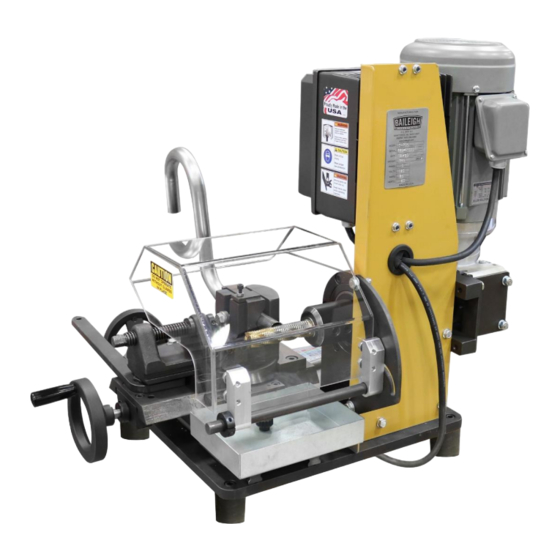
5. Follow the electrical guidelines to connect the machine to a power supply. GETTING TO KNOW YOUR MACHINE • You have made a practical choice in purchasing a Model TN-700 Endmill Notching Machine. It has been carefully built of high quality materials and designed to give many years of efficient service. - Page 15 • The TN-700 Notching Machine you have purchased is built of solid steel and high-quality components, ensuring maximum rigidity and long life.
- Page 16 Item Description Function Used to move the vise bed along the length of the end Y Feed Hand Wheel mill. Release the handle to rotate the vise to the desired Cam Handle angel. Lock the handle to lock the vise at the desired angle.
-
Page 17: Electrical
ELECTRICAL CAUTION: HAVE ELECTRICAL UTILITIES CONNECTED TO MACHINE BY A CERTIFIED ELECTRICIAN! Check if the available power supply is the same as listed on the machine nameplate. WARNING: Make sure the grounding wire (green) is properly connected to avoid electric shock. DO NOT switch the position of the green grounding wire if any electrical plug wires are switched during hookup. -
Page 18: Plug Connection
• Check with a qualified electrician or service personnel if the grounding instructions are not completely understood, or if in doubt as to whether the tool is properly grounded. • Repair or replace damaged or worn cord immediately. Extension Cord Safety Extension cord should be in good condition and meet the minimum wire gauge requirements listed below: LENGTH... -
Page 19: Operation
OPERATION CAUTION: Always wear proper eye protection with side shields, safety footwear, and leather gloves to protect from burrs and sharp edges. WARNING: BEFORE THE MAIN LEXAN GUARD IS OPENED, THE POWER CORD MUST BE UNPLUGGED FROM ITS SOURCE. Cutter Selection 1. -
Page 20: Material Insertion
Material Insertion 1. Once the proper cutter is installed, the material to be notched can be inserted into the vise. 2. Open the vise and insert the material, leaving enough room to extend past the vise jaws for notching. Material should be kept as close as possible to the vise jaws to get the most accurate notch. -
Page 21: Notching
Notching 1. Turn the power switch on and activate the Start button, while making sure the cutter is rotating the correct way. With the cutter rotating, the notch can be created. 2. Slowly turn the "X" handwheel clockwise (CW) to advance the tube to the cutter. Once the cutter just touches the tube, zero out the digital counter. -
Page 22: Angle Notching
Angle Notching To notch at an angle, the vise needs to be rotated left or right. For small angles, rotating to the right is ok, but for large angles, rotating the vise to the left is preferred. IMPORTANT: Never rotate the vise to the right so that the lead screw is in front of the end mill. -
Page 23: Material Selection
MATERIAL SELECTION CAUTION: It must be determined by the customer that materials being processed through the machine are NOT potentially hazardous to operator or personnel working nearby. When selecting materials keep these instructions in mind: • Material must be clean and dry (without oil). •... -
Page 24: Troubleshooting
TROUBLESHOOTING WARNING: Make sure the electrical disconnect is OFF before working on the machine. Problem Solution Material sticking too far out past vise Material not clamped tight in vise Vise lock lever is too loose Chattering Cutter is dull or loose “X”... -
Page 25: Lubrication And Maintenance
LUBRICATION AND MAINTENANCE... -
Page 26: Oil Disposal
Used oil products must be disposed of in a proper manner following your local regulations. Storing Machine for Extended Period of Time If the TN-700 notching machine is to be inactive for a long period of time, prepare the machine as follows: •... -
Page 27: Parts Diagram
PARTS DIAGRAM Base Plate Assembly... -
Page 28: Spindle Assembly
Spindle Assembly... -
Page 29: Motor And Gearbox Assembly
Motor and Gearbox Assembly... -
Page 30: Controller Bracket Assembly
Controller Bracket Assembly... -
Page 31: Vise Base Assembly
Vise Base Assembly... -
Page 32: Y-Axis Assembly
Y-Axis Assembly... -
Page 33: Vise Assembly
Vise Assembly... -
Page 34: Parts List
Parts List Item Part Number Description Qty. TN2500-6001 Base Plate TN2500-6013 Upright Front Rear Upright TN2500-6002 TN2500-7001 Spindle Hub PP-2205 Guide Rail ME-M800-6A073 Slide Base (Top) M800-6A037 Vise Casting TN2500-7002 Spindle ME-M800-6A059 Fixed Vise Clamp Vise Slide Block ME-M800-6A039 "V" Jaw Ass'y For 1'' To 3'' ME-M800-5A005 PP-1076 2 HP 3-Phase Motor... - Page 35 Item Part Number Description Qty. ME-M800-7A025 Shoulder Washer PP-0114 Lock Nut PP-2212 Control Box Drive Assembly W/E-Stop TN2500-6010 Drive Mounting Plate M800-5A015 M800 Guard Assembly PP-2201 .75 X .032 Bearing Washer PP-2203 .75 Thrust Bearing TN2500-5001 X-Axis Lead Screw Assy PP-1272 Electric Counter PP-1763...
- Page 36 M10 X 1.5 X 55 Shcs PP-1710 5.0 Handwheel (.625 Bore) PP-2240 Coupler, White (TN2500 Nord Gearbox) TN2500-7007 1" Reducer Sleeve BAILEIGH INDUSTRIAL 1625 D , WI 54220 UFEK RIVE ANITOWOC : 920. 684. 4990 F : 920. 684. 3944 HONE www.baileigh.com...
Need help?
Do you have a question about the TN-700 and is the answer not in the manual?
Questions and answers