
Subscribe to Our Youtube Channel
Related Manuals for SEW-Eurodrive MAXO-RG-BMS


Summary of Contents for SEW-Eurodrive MAXO-RG-BMS
- Page 1 *259-27779211/EN-02/22* Drive Technology \ Drive Automation \ System Integration \ Services Operating manual [27779211/EN] Communication: Rail bus - mobile side MAXO-RG-BMS Edition 02/2022 259_10030007/EN...
-
Page 3: Table Of Contents
Connections and display elements................10.4 Module connections ....................10.4.1 Connection: X1 - bus connection .............. 10.4.2 Connection: X40 - RS485 interface............10.4.3 Connection: X50 - supply/SYSCAN ............10.5 Displays........................10.6 Type code......................... 10.7 Type plate......................... Operating manual [27779211/EN] - MAXO-RG-BMS... - Page 4 Maintenance ......................... 13.1 Safety information about repairs ................Transport and storage......................14.1 Safety instructions for transport and storage............14.2 Transport inspection ....................Disassembly and disposal....................15.1 Preparation for disassembly ..................15.1.1 Disassembly....................15.2 Disposal........................Index ............................. Operating manual [27779211/EN] - MAXO-RG-BMS...
-
Page 5: Document History
Document history Document history Document history Part number Version Issue Description 27779211/EN 1.01 11/2021 First issue 27779211/EN 1.02 02/2022 Figure „System overview“ updatet; Part number of this document added Operating manual [27779211/EN] - MAXO-RG-BMS... -
Page 6: Abbreviations
Communication type: SMGM (Slotted Microwave Guide Mini) SNMP Simple Network Management Protocol SPS (eng.: PLC Higher-level control Synchronous serial interface SYSCAN System CAN bus UART Universal asynchronous receiver transmitter UDP-IP User Datagram Protocol-Internet Protocol Above sea level Operating manual [27779211/EN] - MAXO-RG-BMS... -
Page 7: General
In addition, the local accident prevention regulations and general safety regulations for the use of the system apply. Illustrations serve basic understand- ing and may deviate from the actual version. Operating manual [27779211/EN] - MAXO-RG-BMS... -
Page 8: Symbols
NOTICE! Residual voltage from charged capacitors!Severe injury. Do not touch any live product parts or power connections. INFORMATION! Residual voltage from charged capacitors!Severe injury. Do not touch any live product parts or power connections. Operating manual [27779211/EN] - MAXO-RG-BMS... - Page 9 Notice text Notice text Notice text Notice text Notice text Notice text Notice text Notice text Notice text Notice text Notice text Notice text Notice text Notice text Notice text No- tice text Notice text Notice text Notice text Notice text Notice text Notice text Notice text Operating manual [27779211/EN] - MAXO-RG-BMS...
-
Page 10: Copyright Protection
We reserve the right to make technical changes to improve usability and for further de- velopment. Customer service SEW-EURODRIVE GmbH & Co KG Ernst-Blickle-Str. 42 Tel: +49 (0) 7251 75-0 Fax: +49 (0) 7251 75- 1970 D - 76646 Bruchsal E-Mail: sew@sew-eurodrive.com Web: www.sew-eurodrive.com Country of origin: Germany Operating manual [27779211/EN] - MAXO-RG-BMS... -
Page 11: Warranty
The warranty period and scope are determined by your contractual conditions and the general delivery conditions of SEW-EURODRIVE GmbH & Co KG. The general warranty and delivery conditions can be viewed on our website. www.sew- eurodrive.com... -
Page 12: Safety Instructions
Further task-related safety instructions are contained in the sections about individual life phases. DANGER ⚠ Danger if the safety instructions are not observed Death or serious injuries • Safety regulations must be strictly observed! Operating manual [27779211/EN] - MAXO-RG-BMS... -
Page 13: Intended Use And Foreseeable Misuse
"Technical data" or on the nameplate. MAXO-RG-BMS communication module is used in systems as a converter of the rail bus signal, which is routed to an EMS Modular. Communication is picked up by a mobile re- ceiver on the system's communication rail. -
Page 14: General Risks
The system must not be changed improperly! WARNING ⚠ Danger from incorrect replacement and dismantling! Accidents and serious injuries • Before starting any dismantling work, safety instructions must be observed. Operating manual [27779211/EN] - MAXO-RG-BMS... -
Page 15: Danger From Electrical Energy
• It must be ensured that components are not live (switch off the voltage) or, if this is not possible, cover the parts with insulating material. • Live parts must be secured against unauthorized approach. Operating manual [27779211/EN] - MAXO-RG-BMS... -
Page 16: Responsibilities Of The Operating Company
The provider must ensure installation and assembly in accordance with EN 60204. • The provider must ensure that all components are disconnected from the power sup- ply in the event of an EMERGENCY STOP. In particular, the power rail installed in parallel. Operating manual [27779211/EN] - MAXO-RG-BMS... -
Page 17: Personnel Requirements
In addition, these persons must have read and understood these safety regulations and must adhere to them afterwards. If required, this may have to be confirmed by the customer/user with a signature. Operating manual [27779211/EN] - MAXO-RG-BMS... -
Page 18: Personal Protective Equipment
If you have long hair, it must be covered (cap, hat, hairnet or similar). Safety harnesses, face and hearing protection according to DGUV regulation 112-189. Ear protection To protect against serious and permanent hearing damage. Operating manual [27779211/EN] - MAXO-RG-BMS... - Page 19 Safety instructions Safety instructions Respiratory protection To protect against serious and permanent diseases of the respiratory tract. Operating manual [27779211/EN] - MAXO-RG-BMS...
-
Page 20: Safety Devices
• Keep access roads open for rescue vehicles. Behavior in case of accidents • Secure the accident site and call first aiders for first aid. • Alert the ambulance service. • Provide first aid. Operating manual [27779211/EN] - MAXO-RG-BMS... -
Page 21: Signage
Always keep all safety, warning and operating instructions in a legible condition. INFORMATION Danger if instructions are not observed Destruction or damage to assemblies • Products may only be used after this document has been completely read and un- derstood! Operating manual [27779211/EN] - MAXO-RG-BMS... -
Page 22: Notes About Hazardous Substances
"POP regulation." Information about hazardous substances according to CP65 (or P65) According to the current state of knowledge, the module does not contain any relevant hazardous substances according to the "CP65 regulation." Operating manual [27779211/EN] - MAXO-RG-BMS... -
Page 23: Applicable Documents
Applicable documents Applicable documents The following documents apply in addition to these instructions: • Operating instructions stationary MAXO-RG-BSx rail bus module • Operating instructions for the EMS Modular control • Technical drawing of the communication module Operating manual [27779211/EN] - MAXO-RG-BMS... -
Page 24: Applied Guidelines, Ordinances And Standards
- Part 1: General requirements DIN EN IEC 63000:2019-05 Technical documentation for providing electrical and electronic equip- ment with regard to hazardous substance restrictions *Guidelines [R], delegated guidelines [DR] and implementing decisions [DB] Operating manual [27779211/EN] - MAXO-RG-BMS... -
Page 25: Technical Data
Depending on the application, industrial environ- ment Installation position Horizontal assembly Installation clearances The actual installation clearances depend on the plugs used and the bending radii of the cables Materials used Housing Aluminum Weight Module weight 0.72 kg Operating manual [27779211/EN] - MAXO-RG-BMS... - Page 26 Interface mobile MAXO communication module - MAXO control Type System CAN bus Cable length < 2 m Connections Connection: X1 - rail bus Type Harting HAN-3A, pin Rotating insert Assignment Rail bus (PCB+, PCB-); grounding conductor Operating manual [27779211/EN] - MAXO-RG-BMS...
- Page 27 Connection: X40 - RS485 interface (absolute value sensor) Type M12, 4 pole, A coded, bushing Assignment RS485 (absolute value sensor), supply voltage for sensor Connection: X50 - supply/SYSCAN Type M12, 8 pole, A coded, pin Assignment Supply, SYSCAN to MAXO control Operating manual [27779211/EN] - MAXO-RG-BMS...
-
Page 28: System Description
System description System description System description The MAXO-RG-BMS module is a mobile rail bus module that is designed for use with MAXO multi-axis controls. The following diagram shows the wiring of such a system as well as the module interfaces. - Page 29 System description System description The MAXO-RG-BMS module acts as a gateway between the rail bus/PCB and the MAXO multi-axis control. Interferences based on the longer route of rail bus to the con- trol unit will be prevented due to implementing the rail bus signal on a system-CAN bus.
-
Page 30: Product Description
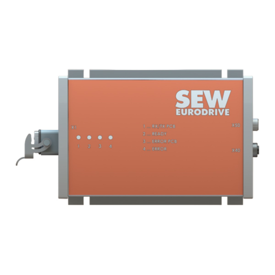
Fig. 10-1 MAXO-RG-BMS module Description The MAXO-RG-BMS is a mobile rail bus module, which is used in connection with an EMS modular control. The module acts as a gateway between the rail bus and multi-axis control. By using the module, disturbances due to long cable lengths - rail bus to multi- axis control - are minimized. -
Page 31: Mechanical Dimensions
Danger due to poor mounting Injuries as well as property damage and malfunctions • The module must be secured using the four mounting tabs. Ensure that the mount- ing cannot come loose due to vibrations. Operating manual [27779211/EN] - MAXO-RG-BMS... -
Page 32: Connections And Display Elements
Overview: LED displays - LED bar (“LEDs“) The arrangement of the LED bar is shown on the front of the module. Position Function Description RX/TX PCB Rail bus communication READY Mode of operation ERROR PCB Rail bus error ERROR Error display Operating manual [27779211/EN] - MAXO-RG-BMS... -
Page 33: Module Connections
Fig. 10-4 Connection X1 (in mounting position) Type Description Note Connection X1 Harting HAN-3A, pin Interface Rail bus, protective conductor Function Note PCB+ Rail bus + PCB- Rail bus - n.c. Not connected Protective conductor Operating manual [27779211/EN] - MAXO-RG-BMS... -
Page 34: Connection: X40 - Rs485 Interface
Fig. 10-5 Connection X40 Type Description Note Connection X40 M12, 4 pole, A coded, bushing Interface Absolute value sensor Cable length < 3 m (sensor cable) Function Note Supply voltage +24 VDC RS485_A Communication Supply ground RS485_B Communication Operating manual [27779211/EN] - MAXO-RG-BMS... -
Page 35: Connection: X50 - Supply/Syscan
Supply voltage, system CAN bus for MAXO control unit Function Note Supply voltage +24VDC Not connected Supply ground CAN_H System CAN bus HIGH CAN_L System CAN bus LOW CAN_GND System CAN bus ground Not connected Not connected Operating manual [27779211/EN] - MAXO-RG-BMS... -
Page 36: Displays
LED2: READY - operational Color Status Description Green Flashes MAXO-RG- BMS-module not yet or not completely configured. Green Duration MAXO-RG-BMS module completely configured and operation- LED3: ERROR PCB - Rail bus error Color Status Description Flashes Rail bus error: • CAN status (BusOff) •... -
Page 37: Type Code
Product description Product description 10.6 Type code Operating manual [27779211/EN] - MAXO-RG-BMS... -
Page 38: Type Plate
Machine readable material number (scanner) ####: Production date Designation of standards etc. (in this case CE) Crossed out garbage can Symbol for separate collection / collection of elec- tronic waste (according to WEEE Directive 2012/ 19/EU) Operating manual [27779211/EN] - MAXO-RG-BMS... -
Page 39: Ordering Overview
Product description Product description 10.8 Ordering overview Designation Description Item No. MAXO-RG-BMS-A-01 Mobile rail bus module, for use 25740822 with MAXO multi-axis control Scope of delivery: • Module without accessories Operating manual [27779211/EN] - MAXO-RG-BMS... -
Page 40: Assembly & Commissioning
Please note that other system components (control unit, bus bars, etc.) can also car- ry hazardous voltages. • It is mandatory to ground the MAXO-RG-BMS module via X1 to prevent personal in- jury and operating failures. Operating manual [27779211/EN] - MAXO-RG-BMS... -
Page 41: Emc
Information about adhering to the EMC requirements The user is responsible for adhering to the EMC directive in the machine application. Operating manual [27779211/EN] - MAXO-RG-BMS... -
Page 42: Connection Examples For X1 Connection
Connection examples for X1 connection Fig. 11-1 Connection examples for X1 The Harting connector plugs shown are not part of the scope of delivery. The Harting insert on the MAXO-RG-BMS module can not be rotated. Operating manual [27779211/EN] - MAXO-RG-BMS... -
Page 43: Operation
Information about configuration mode If the MAXO-RG-BMS module is in configuration mode, it does not read any data from the absolute value sensor and does not work as a gateway between the rail bus and the internal CAN system bus. -
Page 44: Parameterization
Parameters shown below must be configured. The description of the parameters can be found in the MOVI-C® CONTROL manual. The MAXO-RG-BMS module is configured by the control (= CAN master) via the internal system CAN bus, via acyclic SDO telegrams. -
Page 45: Malfunctions
Inspection and maintenance work described in this technical documentation must be carried out on a regular basis and documented: (location, spare part, work carried out, date, inspector's name). System fault elimination may only be carried out by trained, qualified and authorized per- sons. Operating manual [27779211/EN] - MAXO-RG-BMS... -
Page 46: Error Messages
Malfunctions 12.3 Error messages Error messages can be read from the LEDs of the MAXO-RG-BMS module (see section: “"Displays" ( 34)“) Information about status and error messages Additional status and error messages are shown on the display of the vehicle control. -
Page 47: Return/Repair
Designation of the system in which the assembly is installed • Name of a contact person (for poss. questions) • Module designation and serial number • Error description (which defective pattern was identified? Under which cir- cumstances does the error occur?) Operating manual [27779211/EN] - MAXO-RG-BMS... -
Page 48: Maintenance
(location, spare part, work carried out, date, inspector's name). System fault elimination may only be carried out by trained, qualified and authorized per- sons. Date Name Maintenance and ser- Instructions are Signature vicing work given by Operating manual [27779211/EN] - MAXO-RG-BMS... -
Page 49: Safety Information About Repairs
Danger - stumbling due to protruding components Injuries • When entering the work and danger area, pay attention to steps and depressions in the floor. There must be no loose objects in the work area. Operating manual [27779211/EN] - MAXO-RG-BMS... -
Page 50: Transport And Storage
Obvious transport damage must be reported to the transport company immediately or acceptance with reservation. It is at recipient's discretion to refuse delivery accep- tance in the event of transport damage. • All defects must be documented and reported to the manufacturer. Operating manual [27779211/EN] - MAXO-RG-BMS... -
Page 51: Disassembly And Disposal
Before starting any dismantling work, the safety instructions must be observed. CAUTION ⚠ All accessories must be checked for wear! Only parts in perfect condition may be used again. • Only original SEW spare parts may be used. Operating manual [27779211/EN] - MAXO-RG-BMS... -
Page 52: Disposal
• The provider, as a professional user of the products, is responsible for the proper disposal or recycling of the (old) products. • Contact a recovery, recycling or disposal company that specializes in electronic waste. Operating manual [27779211/EN] - MAXO-RG-BMS... - Page 53 The product may not be disposed of in unsorted waste, but must be brought to sep- arate collection points for disposal / recovery (recycling). • The black bar under the symbol indicates the product was placed on the market after August 13, 2005. Operating manual [27779211/EN] - MAXO-RG-BMS...
-
Page 54: Index
Information about the instructions ......5 Mains voltage information ........38 Mechanical dimensions........29 Module overview ..........30 Repair ..............45 safety aspects ............ 10 Switching On ............41 Symbol explanations ..........6 system overview..........26 Operating manual [27779211/EN] - MAXO-RG-BMS...
Need help?
Do you have a question about the MAXO-RG-BMS and is the answer not in the manual?
Questions and answers