SEW-Eurodrive Movidrive MD_60A Series Operating Instructions Manual
Hide thumbs
Also See for Movidrive MD_60A Series:
- System manual (310 pages) ,
- Addendum to the system manual (52 pages) ,
- Manual (46 pages)
Table of Contents
Advertisement
Advertisement
Table of Contents

Related Manuals for SEW-Eurodrive Movidrive MD_60A Series


Summary of Contents for SEW-Eurodrive Movidrive MD_60A Series
- Page 1 DATASHEET SEW EURODRIVE MDF60A0030-5A3-4-00 OTHER SYMBOLS: RGB ELEKTRONIKA AGACIAK CIACIEK SPÓŁKA JAWNA Jana Dlugosza 2-6 Street 51-162 Wrocław www.rgbelektronika.pl Poland biuro@rgbelektronika.pl +48 71 325 15 05 www.rgbautomatyka.pl www.rgbautomatyka.pl www.rgbelektronika.pl...
- Page 2 YOUR PARTNER IN MAINTENANCE Repair this product with RGB ELEKTRONIKA ORDER A DIAGNOSIS LINEAR ENCODERS SYSTEMS INDUSTRIAL COMPUTERS ENCODERS CONTROLS SERVO AMPLIFIERS MOTORS MACHINES OUR SERVICES POWER SUPPLIERS OPERATOR SERVO PANELS DRIVERS At our premises in Wrocław, we have a fully equipped servicing facility. Here we perform all the repair works and test each later sold unit.
- Page 3 Edition ® MOVIDRIVE MD_60A 09/2001 Operating Instructions 1053 2617 / EN...
- Page 4 SEW-EURODRIVE...
-
Page 5: Table Of Contents
1 Important Notes...................... 4 2 Safety Notes ......................6 3 Unit Design ......................7 Unit designation, nameplates and scope of supply........7 Unit design, size 1..................8 Unit design, size 2..................9 Unit design, size 3..................10 Unit design, size 4..................11 Unit design, size 5.................. -
Page 6: Important Notes
Important Notes Safety and Always follow the safety and warning instructions contained in this publication! warning instructions Electrical hazard Possible consequences: Severe or fatal injuries. Hazard Possible consequences: Severe or fatal injuries. Hazardous situation Possible consequences: Slight or minor injuries. Harmful situation Possible consequences: Damage to the unit and the environment. - Page 7 Application The following uses are forbidden unless measures are expressly taken to make environment them possible: • Use in explosion-proof areas • Use in areas exposed to harmful oils, acids, gases, vapors, dust, radiation, etc. • Use in non-stationary applications which are subject to mechanical vibration and shock loads in excess of the requirements in EN 50178 Safety functions ®...
-
Page 8: Safety Notes
Safety Notes Installation and • Never install damaged products or take them into operation.Please submit a startup complaint to the transport company immediately in the event of damage. • Installation, startup and service work only by trained personnel observing applicable accident prevention regulations and operating instructions! The regulations in force (e.g. -
Page 9: Unit Design
Unit designation, nameplates and scope of supply Unit Design Unit designation, nameplates and scope of supply Sample unit designation MOVIDRIVE MDV 60 A 0055-5A3-4-00 ® Version 00 = Standard / 0T = Applications Quadrants 4 = 4Q (with brake chopper) 3 = 3-phase Type of supply Input filter... -
Page 10: Unit Design, Size 1
Unit design, size 1 Unit design, size 1 MD_60A-5A3 (400/500 V units): 0015 – 0040 MD_60A-2A3 (230 V units): 0015 – 0037 01245BXX ® Fig. 4: Unit design, MOVIDRIVE size 1 1. X1: Mains connection L1 (1) / L2 (2) / L3 (3), separable 2. -
Page 11: Unit Design, Size 2
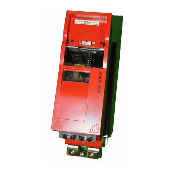
Unit design, size 2 Unit design, size 2 MD_60A-5A3 (400/500 V units): 0055 – 0110 MD_60A-2A3 (230 V units): 0055 / 0075 00895BXX ® Fig. 5: Unit design, MOVIDRIVE size 2 1. X1: Mains connection L1 (1) / L2 (2) / L3 (3) 2. -
Page 12: Unit Design, Size 3
Unit design, size 3 Unit design, size 3 MD_60A-503 (400/500 V units): 0150 – 0300 MD_60A-203 (230 V units): 0110 / 0150 01248BXX ® Fig. 6: Unit design, MOVIDRIVE size 3 1. PE connections 2. X1: Mains connection L1 (1) / L2 (2) / L3 (3) 3. -
Page 13: Unit Design, Size 4
Unit design, size 4 Unit design, size 4 MD_60A-503 (400/500 V units): 0370 / 0450 MD_60A-203 (230 V units): 0220 / 0300 01249BXX ® Fig. 7: Unit design, MOVIDRIVE size 4 1. X2: PE connection 2. X1: Mains connection L1 (1) / L2 (2) / L3 (3) 3. -
Page 14: Unit Design, Size 5
Unit design, size 5 Unit design, size 5 MD_60A-503 (400/500 V units): 0550 / 0750 01249BXX ® Fig. 8: Unit design, MOVIDRIVE size 5 1. X2: PE connection 2. X1: Mains connection L1 (1) / L2 (2) / L3 (3) 3. -
Page 15: Installation
Installation instructions for basic unit Installation Installation instructions for basic unit It is essential to comply with the safety notes during installation! Tightening • Only use genuine connection elements. Note the permitted tightening torques ® torques of MOVIDRIVE power terminals. →... - Page 16 Installation instructions for basic unit Separate cable • Route power cables and electronics cables in separate cable ducts. ducts Input fuses and • Install the input fuses at the beginning of the supply system lead behind the earth-leakage supply bus junction (→ Wiring diagram for basic unit, power section and brake). circuit breakers •...
- Page 17 Installation instructions for basic unit Connecting • Use two closely twisted cables or a 2-core shielded power cable. Cross section braking resistors according to the output rated current of the inverter. • Protect the braking resistor with a bimetallic relay (→ Wiring diagram for basic unit, power section and brake).
- Page 18 Installation instructions for basic unit Input filter • Sizes 1 and 2 are fitted with an input filter as standard. This input filter ensures that limit value class A is maintained on the supply side. Use an NF...-... input filter as an option to maintain the class B limit.
-
Page 19: Ul Compliant Installation
UL compliant installation UL compliant installation Please note the following points for UL compliant installation: • Only use copper cables with the following temperature ranges as connection leads: ® • For MOVIDRIVE MD_60A0015 – 0300 temperature range 60/75 °C ® •... -
Page 20: Power Shield Clamp
Power shield clamp Power shield clamp ® For size 1 A power shield clamp is supplied as standard with MOVIDRIVE size 1. Install this power shield clamp together with the retaining screws of the unit. 02012BXX ® Fig. 14: Power shield clamp for MOVIDRIVE size 1 1. -
Page 21: Touch Guard
Touch guard Touch guard Two touch guards and eight retaining screws are supplied as standard with ® MOVIDRIVE size 4 (500 V units: MD_60A0370/0450; 230 V units: MD_60A0220/0300) and size 5 (MD_60A0550/0750). Install the touch guard on the two hood covers for the power section terminals. -
Page 22: Wiring Diagram, Basic Unit
Wiring diagram, basic unit Wiring diagram, basic unit Connection of the power section and brake F11/F12/F13 Protective earth conductor (shield) (AC-3) L1 L2 Option NF... input filter DC-link L1' L2' L3' connection F14/F15 F14/F15 F14/F15 L1 L2 L3 DC link DC link Power section (AC-3) - Page 23 Wiring diagram, basic unit Control unit connection Control unit X11: -10V...+10V 0(4)...20mA CONTROL +10V REF1 0V5 - + AI11 n1 (0...10V*;+/-10V; RS485 AI12 0...20mA;4...20mA) Ref.potential for analog signals AGND RS232 -10V REF2 ↔ Select: I signal V signal* Option S 11 Option S 12 system bus terminating resistor...
- Page 24 Wiring diagram, basic unit Functional description of the terminals of the basic unit (power section and control unit) Terminal Function L1/L2/L3 X1:1/2/3 Mains connection X2:4/5/6 U/V/W Motor connection X3:8/9 +R/-R Braking resistor connection DC link connection X11:1 REF1 +10 V (max. 3 mA) for setpoint potentiometer Setpoint input n1 (differential input or input with AGND reference potential), signal form →...
-
Page 25: Assignment Of Braking Resistors, Chokes And Filters
Assignment of braking resistors, chokes and filters Assignment of braking resistors, chokes and filters 400/500 V units, sizes 1 and 2 ® MOVIDRIVE MD_60A...-5A3 0015 0022 0030 0040 0055 0075 0110 Size Braking resistors Trip current Part number BW100-005 = 0.8 A 826 269 1 BW100-006 = 1.8 A... - Page 26 Assignment of braking resistors, chokes and filters 400/500 V units, sizes 3 to 5 ® MOVIDRIVE MD_60A...-503 0150 0220 0300 0370 0450 0550 0750 Size Braking resistors Trip current Part number BW018-015 = 4.0 A 821 684 3 BW018-035 = 8.1 A 821 685 1 BW018-075 = 14 A...
- Page 27 Assignment of braking resistors, chokes and filters 230 V units, sizes 1 to 4 ® MOVIDRIVE MD_60A...-2_3 0015 0022 0037 0055 0075 0110 0150 0220 0300 Size Braking resistors Trip current Part number BW039-003 = 2.0 A 821 687 8 BW039-006 = 3.2 A 821 688 6...
-
Page 28: System Bus (Sbus) Connection
System bus (SBus) connection System bus (SBus) connection Max. 64 CAN bus stations can be interconnected using the system bus (SBus). The SBus supports transmission systems compliant with ISO 11898. The "System Bus (SBus)" manual contains detailed information about the system bus. This manual can be obtained from SEW. -
Page 29: Rs-485 Interface Connection
RS-485 interface connection RS-485 interface connection ® The RS-485 interface can be used for connecting max. 32 MOVIDRIVE units, e.g. for ® master/slave operation, or 31 MOVIDRIVE units and a CAN machine control (PLC). Wiring diagram, RS-485 interface Control unit Control unit Control unit X13:... -
Page 30: Connection Option Uss21A (Rs-232 And Rs-485)
Connection option USS21A (RS-232 and RS-485) Connection option USS21A (RS-232 and RS-485) Part number USS21A: 822 914 7 RS-232 • Use a shielded standard interface cable for connecting to the RS-232 interface. connection USS21A PC COM 1-4 GND (ground) max. 5 m (16.5 ft) 9-pin sub D connector (male) 9-pin sub D connector (female) 02399AEN... -
Page 31: Combination Of Options
Combinations of options 4.10 Combinations of options The following tables show the possible combinations of options in the status as supplied. The meaning of the individual table entries is as follows: The options cannot be used in conjunction with one another. Connect the option in the first column (↓) to the OPTION1 slot. -
Page 32: Installing And Removing Option Pcbs
Installing and removing option pcbs 4.11 Installing and removing option pcbs Before you begin • Take suitable measures to dissipate any electrical charge in your body before you touch the option pcb (discharge strap, conductive shoes, etc.). • Keep the option pcb in its original packaging and do not remove it until just before installing it. - Page 33 Installing and removing option pcbs Removing the • Disconnect inverter from the supply system, switch off supply system and 24 V option pcb • Remove the keypad, serial interface or blank panel. • Remove the lower hood cover from the control unit. •...
-
Page 34: Connection And Terminal Description Of The Dio11A Option
Connection and terminal description of the DIO11A option 4.12 Connection and terminal description of the DIO11A option Part number Terminal expansion board option type DIO11A: 822 726 8 Front view of DIO11A Terminal Function X20:1/2 AI21/22 Setpoint input n2, -10 V – 0 – 10 V or 0 – 10 V (Differential input or input with AGND reference potential) X20:3 AGND... - Page 35 Connection and terminal description of the DIO11A option Current input You must use an external load if the analog setpoint input n2 (AI21/22) should be used as a current input. = 500 Ω → 0 – 20 mA = 0 – 10 V For example R 0...20 mA AI21...
-
Page 36: Encoder And Resolver Connection
Encoder and resolver connection 4.13 Encoder and resolver connection The "SEW Encoder Systems" manual contains detailed information. This manual can be obtained from SEW. General • Max. line length of inverter – encoder/resolver: 100 m (330 ft) with a capacitance per unit length ≤... - Page 37 Encoder and resolver connection ® Motor encoder The following motor encoders may be connected to X15: of MOVIDRIVE MDV60A units: • High-resolution sin/cos encoders with signal voltage 1 V • 5 V TTL sensors with signal level to RS-422 • 24 V HTL sensors 01936AXX Fig.
- Page 38 Encoder and resolver connection 5 V TTL sensors 5 V TTL sensors from SEW are available with a 24 V voltage supply and a 5 V voltage supply. 24 V voltage Connect 5 V TTL sensors to the 24 V voltage supply ES1R, ES2R or EV1S in the supply same way as the high-resolution sin/cos encoders.
- Page 39 Encoder and resolver connection HTL sensors If you are using a 24 V HTL sensor ES1C, ES2C or EV1C, you are not allowed to connect the negated channels A (K1), B (K2) and C (K0). max. 100 m (330 ft) ES1C / ES2C / EV1C X15: A (K1)
- Page 40 Encoder and resolver connection Connection to the Connect the absolute encoder AV1Y to the DIP11A option as follows: DIP11A option DIP11A max. 100 m (330 ft) AV1Y X62: (N.C.) 2 (N.C.) 4 (N.C.) 7 03978AXX Fig. 37: Connecting AV1Y to DIP11A ®...
- Page 41 Encoder and resolver connection Resolver SEW offers the following pre-fabricated cables for connecting resolvers to ® MOVIDRIVE MDS60A: Part number For motor type Fixed routing Cat track routing CM71 – 112 with pl. connection 199 214 7 199 215 5 with terminal box 198 829 8 198 828 X...
- Page 42 Encoder and resolver connection External Only encoders with a signal level according to RS-422 (5 V-TTL) are allowed to be ® encoders connected to X14: of MOVIDRIVE MDV/MDS units. Voltage supply Encoders with 24 V voltage supply (max. 180 mA) are connected directly to X14:. These encoders are then powered by the inverter.
- Page 43 Encoder and resolver connection Encoder ES1R / ES2R EV1R → MOVIDRIVE ® Part numbers of X14: (Fig. 141) the pre-fabricated Only fixed routing: 815 354 X cables Encoder ES1T /ES2T / EV1T → DWI11A X2: encoder (Fig. 142) For fixed routing: 198 829 8 For cat track routing: 198 828 X...
- Page 44 Encoder and resolver connection ® Master/slave X14 – X14 connection (= master/slave connection) of two MOVIDRIVE units. connection Connection Master Slave ® ® MOVIDRIVE MOVIDRIVE max. 100 m (330 ft) X14: X14: 05036AXX Fig. 43: X14 – X14 connection Part number of the pre-fabricated Only fixed routing: 815 355 8...
-
Page 45: Startup
General startup instructions Startup General startup instructions It is essential to comply with the safety notes during startup! Requirements Correct project planning of the drive is the pre-requisite for successful startup. Refer to ® the MOVIDRIVE system manual for detailed project planning instructions and an explanation of the parameters (chapters 4 and 5). - Page 46 General startup instructions 230 V units ® MOVIDRIVE MDF60A SEW motor or MDV60A in VFC mode 0015-2A3-4 DT90L4 0022-2A3-4 DV100LS4 0037-2A3-4 DV100L4 0055-2A3-4 DV132S4 0075-2A3-4 DV132M4 0110-203-4 DV160M4 0150-203-4 DV180M4 0220-203-4 DV180L4 0300-203-4 DV225S4 The startup functions described in this section are used for setting the inverter so it is optimally adapted to the motor which is actually connected and to the given boundary conditions.
-
Page 47: Preliminary Work And Resources
Preliminary work and resources Preliminary work and resources • Check installation. • Take suitable measures to prevent the motor starting up inadvertently, for example by removing the electronics terminal block X13:. Furthermore, additional safety precautions must be taken depending on the application in order to avoid endangering people and machinery. -
Page 48: Startup With The Dbg11A Keypad
Startup with the DBG11A keypad Startup with the DBG11A keypad General Startup with the DBG11A keypad is only possible with MDF and MDV in VFC information operating modes. Startup in CFC and SERVO operating modes is only possible using the MOVITOOLS software. Data required The following data are required for successful startup: •... - Page 49 Startup with the DBG11A keypad Detailed description of the keypad → Sec. "Operating displays": Startup functions of the DBG11A ← and → at the same Commence startup. time ↑ Next menu command or increase value in edit mode. Previous menu command or decrease value in edit ↓...
- Page 50 Startup with the DBG11A keypad Structure of the startup menu CONTR. INHIBIT CURR.: ← → [ ] and [ ] simultaneously → STARTUP -> PREPARE FOR IPOS_VARIABLES <- STARTUP ca. 3 s C0 * PARAM. SET 1 STARTUP [ ] ↑ →...
- Page 51 Startup with the DBG11A keypad Startup procedure 1. "0" signal at terminal X13:1 (DIØØ "/CONTROL.INHIBIT"), e.g. CONTROL.INHIBIT CURRENT: by disconnecting the electronics terminal block X13. 2. Activate the startup menu by pressing the ← and → keys on STARTUP → IPOS_VARIABLES ←...
- Page 52 Startup with the DBG11A keypad 11. If no TF/TH is connected to X10:1 and X10:2 → Set "NO 835* NO RESP. RESP. TF sens SIGNAL RESP.". Set the required fault response if a TF/TH is connected. 12. Commence the startup calculation by selecting "YES". C06* CALCULATION WITH SEW MOTORS...
- Page 53 Startup with the DBG11A keypad Startup of speed Startup without the speed controller is performed first. controller Important: Set VFC-n-CONTROL operating mode. C01* VFC-n-CTRL OPER. MODE 1 Structure Structure of the startup menu for the speed controller: C 0 9 * C O M I S S .
- Page 54 Startup with the DBG11A keypad Startup procedure 1. Press "YES" to commence the speed controller startup. All mass moments of inertia must be entered in the unit [10 2. Press the ↑ key to move on to the next menu item each time. 3.
-
Page 55: Startup With A Pc And Movitools
Startup with a PC and MOVITOOLS Startup with a PC and MOVITOOLS General • Terminal X13:1 (DIØØ "/CONTROL.INHIBIT") must get a "0" signal! information • Start the MOVITOOLS program. • Set the language. • Select the PC port (PC COM) to which the inverter is connected. •... -
Page 56: Starting The Motor
Starting the motor Starting the motor Analog setpoint The following table shows which signals must be present on terminals X11:2 (AI1) and specification X13:1 – X13:4 (DIØØ – DIØ3) when the "UNIPOL/FIX.SETPT" setpoint is selected (P100), in order to operate the drive with an analog setpoint entry. X11:2 (AI11) X13:1 (DIØØ) X13:2 (DIØ1) - Page 57 Starting the motor Fixed setpoints The following table shows which signals must be present on terminals X13:1 – X13:6 (DIØØ – DIØ5) when the "UNIPOL/FIX.SETPT" setpoint is selected (P100), in order to operate the drive with the fixed setpoints. X13:1 (DIØØ) X13:2 (DIØ1) X13:3 (DIØ2) X13:4 (DIØ3)
- Page 58 Starting the motor Manual operation The inverter can be controlled using the DBG11A keypad using the manual operation function. The 7-segment display on the unit shows "H" during manual mode. In order for manual operation to be started, there must be a "0" signal sent to binary inputs X13:2 (DIØ1) "CW/stop", X13:3 (DIØ2 "CCW/stop") and X13:4 (DIØ3 "Enable/ rapid stop"), if programmed.
-
Page 59: Complete Parameter List
Complete parameter list Complete parameter list The parameters of the short menu are identified by a "/" (= displayed on the DBG11A keypad). Par. Name Value range Par. Name Value range DISPLAY VALUES Binary outputs option Process values Binary output DO1Ø Speed -5000 –... - Page 60 Complete parameter list Name Name Setting range After Setting range After Par. Par. Variable par. Factory setting startup Factory setting startup Parameter set 2 Parameter set 1 SETPOINTS / RAMP GENERATORS Setpoint selection 100/ Setpoint source UNIPOL/FIX.SETPT Control signal source TERMINALS Analog input AI1 AI1 scaling...
- Page 61 Complete parameter list Name Name Setting range After Setting range After Par. Par. Variable par. Factory setting startup Factory setting startup Parameter set 2 Parameter set 1 CONTROLLER PARAMETERS Speed control (only parameter set 1) P gain speed controller 0.1 – 2 – 32 Time constant n- 0 –...
- Page 62 Complete parameter list Name Name Setting range After Setting range After Par. Par. Variable par. Factory setting startup Factory setting startup Parameter set 2 Parameter set 1 MOTOR PARAMETERS Limits 1 31_ Limits 2 300/ Start/stop speed 1 0 – 60 – 150 rpm 310 Start/stop speed 2 0 –...
- Page 63 Complete parameter list Name Name Setting range After Setting range After Par. Par. Variable par. Factory setting startup Factory setting startup Parameter set 2 Parameter set 1 MONITORING FUNCTIONS Speed monitoring OFF / MOTOR MODE / OFF / MOTOR MODE / Speed Speed REGENERAT.
- Page 64 Complete parameter list Name Name Setting range After Setting range After Par. Par. Variable par. Factory setting startup Factory setting startup Parameter set 2 Parameter set 1 Analog outputs optional Analog output AO1 ACTUAL SPEED Scaling AO1 -10 – 0 – 1 – 10 The following functions can be programmed: NO FUNCTION •...
- Page 65 Complete parameter list Name Name Setting range After Setting range After Par. Par. Variable par. Factory setting startup Factory setting startup Parameter set 2 Parameter set 1 UNIT FUNCTIONS Setup 802/ Factory setting YES / NO 803/ Parameter lock ON / OFF NO FAULT MEMORY Reset statistic data KWH-METER...
- Page 66 Complete parameter list Name Name Setting range After Setting range After Par. Par. Variable par. Factory setting startup Factory setting startup Parameter set 2 Parameter set 1 Modulation PWM frequency 1 4/8/12/16 kHz 861 PWM frequency 2 4/8/12/16 kHz PWM fix 1 ON / OFF 863 PWM fix 2 ON / OFF...
- Page 67 Complete parameter list Name Name Setting range After Setting range After Par. Par. Variable par. Factory setting startup Factory setting startup Parameter set 2 Parameter set 1 IPOS Variables/Encoder This parameter is only available in the DBG11A keypad, not in IPOS variables edit ON / OFF MOVITOOLS!
-
Page 68: Operation And Service
Operating displays Operation and Servicing Operating displays ® 7-segment The 7-segment display shows the operating status of MOVIDRIVE in hexadecimal display notation and, in the event of a fault, a fault or warning code. Display Meaning Inverter not ready Controller inhibit active No enable Current at standstill VFC mode... - Page 69 Operating displays Copy function of The DBG11A keypad can be used for copying complete parameter sets from one ® ® the DBG11A MOVIDRIVE unit to another MOVIDRIVE . To do this, copy the parameter set onto the keypad using P807 (MD_ → DBG). Connect the keypad to another MOVIDRIVE ®...
- Page 70 Operating displays Quick menu of The DBG11A keypad has a detailed parameter menu and a clearly structured quick the DBG11A menu with the most frequently used parameters. It is possible to switch between both menus using P800 ("Quick menu"). This can be done in any operating status. The default setting is for the quick menu to be active.
- Page 71 Operating displays Information Information messages on the DBG11A (approx. 2 s in duration) or in MOVITOOLS/ messages SHELL (message which can be acknowledged): No. Text DBG11A/SHELL Description ILLEGAL INDEX Index addressed via interface is not available. • Attempt to execute a non-implemented function. NOT IMPLEMENTED •...
-
Page 72: Fault Information
Fault information Fault information Fault memory The fault memory (P080) stores the last five fault messages (faults t-0 – t-4). The fault message of longest standing is deleted whenever more than five fault messages have occurred. The following information is stored when a malfunction takes place: Fault which occurred •... -
Page 73: Error Messages And List Of Faults
Fault messages and list of faults Fault messages and list of faults Fault message on The fault or warning code is displayed in BCD format. The following display sequence 7-segment is adhered to (e.g. fault code 84): display Flashes, approx. 1 s Display off, approx. - Page 74 Fault messages and list of faults Fault Description Reaction P Possible cause Measure code • Reduce load • Speed controller or current controller (in • Increase deceleration time setting (P501 VFC operating mode without encoder) or P503) operating at setting limit due to •...
- Page 75 Fault messages and list of faults Fault Description Reaction P Possible cause Measure code • Use correct option pcb • Type of option pcb not allowed • Set correct setpoint source (P100) • Setpoint source, control source or Immediate • Set correct control signal source (P101) No option operating mode not permitted for this...
- Page 76 Fault messages and list of faults Fault Description Reaction P Possible cause Measure code Only with DPx11A: No reference Reference travel not performed with "GO0" or Perform reference travel. travel response "SET0" command. Only with DPx11A: Machine Incorrect input of a machine parameter (e.g. Check machine parameter and correct it.
- Page 77 Fault messages and list of faults Fault Description Reaction P Possible cause Measure code Timeout DPx- Coded fault; only with DPA11A. response Code 1: SSI interface fault. SSI module defective. Inform SEW Service if fault cannot be reset or Code 2: Communication if it occurs frequently.
- Page 78 Fault messages and list of faults Fault Description Reaction P Possible cause Measure code Only with DIP11A option: The encoder signals a fault, e.g. power failure. • Connection cable between the encoder • Check absolute encoder connection and DIP does not meet the requirements •...
-
Page 79: Sew Electronics Service
SEW electronics service SEW electronics service Send in for repair Please contact the SEW electronics service if a fault cannot be rectified (→ "Customer and spare parts service"). When contacting the SEW electronics service, please always quote the digits of your service code to enable our service personnel to assist you more effectively. -
Page 80: P Hz
General technical data Technical Data General technical data ® The following table lists the technical data applicable to all MOVIDRIVE MD_60A drive inverters, regardless of type, version, size and performance. ® MOVIDRIVE MD_60A All sizes Interference immunity To EN 61800-3 Interference emission with EMC- According to class B limit to EN 55011 and EN 55014 compliant installation... -
Page 81: Movidrive® Md_60A
MOVIDRIVE® MD_60A...-5_3 (400/500 V units) ® MOVIDRIVE MD_60A...-5_3 (400/500 V units) Size 1 ® MOVIDRIVE MD_60A 0015-5A3-4-0_ 0022-5A3-4-0_ 0030-5A3-4-0_ 0040-5A3-4-0_ INPUT 3 × 380 V -10 % – 3 × 500 V Supply voltage +10 % 50 Hz – 60 Hz ±5 % Supply frequency Rated system current 100 %... - Page 82 MOVIDRIVE® MD_60A...-5_3 (400/500 V units) Size 2 ® MOVIDRIVE MD_60A 0055-5A3-4-0_ 0075-5A3-4-0_ 0110-5A3-4-0_ INPUT 3 × 380 V -10 % – 3 × 500 V Supply voltage +10 % 50 Hz – 60 Hz ±5 % Supply frequency Rated system current 100 % 11.3 A 14.4 A...
- Page 83 MOVIDRIVE® MD_60A...-5_3 (400/500 V units) Size 3 ® MOVIDRIVE MD_60A 0150-503-4-0_ 0220-503-4-0_ 0300-503-4-0_ INPUT 3 × 380 V -10 % – 3 × 500 V Supply voltage +10 % 50 Hz – 60 Hz ±5 % Supply frequency Rated system current 100 % 28.8 A 41.4 A...
- Page 84 MOVIDRIVE® MD_60A...-5_3 (400/500 V units) Size 4 ® MOVIDRIVE MD_60A 0370-503-4-0_ 0450-503-4-0_ INPUT 3 × 380 V -10 % – 3 × 500 V Supply voltage +10 % 50 Hz – 60 Hz ±5 % Supply frequency Rated system current 100 % 65.7 A 80.1 A...
- Page 85 MOVIDRIVE® MD_60A...-5_3 (400/500 V units) Size 5 ® MOVIDRIVE MD_60A 0550-503-4-0_ 0750-503-4-0_ INPUT 3 × 380 V -10 % – 3 × 500 V Supply voltage +10 % 50 Hz – 60 Hz ±5 % Supply frequency Rated system current 100 % 94.5 A 117.0 A...
-
Page 86: Movidrive ® Md_60A
MOVIDRIVE® MD_60A...-2_3 (230 V units) ® MOVIDRIVE MD_60A...-2_3 (230 V units) Size 1 ® MOVIDRIVE MD_60A 0015-2A3-4-0_ 0022-2A3-4-0_ 0037-2A3-4-0_ INPUT 3 × 200 V -10 % – 3 × 240 V Supply voltage +10 % 50 Hz – 60 Hz ±5 % Supply frequency Rated system current I 100 %... - Page 87 MOVIDRIVE® MD_60A...-2_3 (230 V units) Size 2 ® MOVIDRIVE MD_60A 0055-2A3-4-0_ 0075-2A3-4-0_ INPUT 3 × 200 V -10 % – 3 × 240 V Supply voltage +10 % 50 Hz – 60 Hz ±5 % Supply frequency Rated system current I 100 % 19.5 A 27.4 A...
- Page 88 MOVIDRIVE® MD_60A...-2_3 (230 V units) Size 3 ® MOVIDRIVE MD_60A 0110-203-4-0_ 0150-203-4-0_ INPUT 3 × 200 V -10 % – 3 × 240 V Supply voltage +10 % 50 Hz – 60 Hz ±5 % Supply frequency Rated system current I 100 % 40.0 A 49.0 A...
- Page 89 MOVIDRIVE® MD_60A...-2_3 (230 V units) Size 4 ® MOVIDRIVE MD_60A 0220-203-4-0_ 0300-203-4-0_ INPUT 3 × 200 V -10 % – 3 × 240 V Supply voltage +10 % 50 Hz – 60 Hz ±5 % Supply frequency Rated system current I 100 % 72 A 86 A...
-
Page 90: Movidrive® Md_60A Electronics Data
MOVIDRIVE® MD_60A electronics data ® MOVIDRIVE MD_60A electronics data ® MOVIDRIVE MD_60 General electronics data Voltage supply X11:1 REF1: +10 V +5 % / -0 %, I = 3 mA Reference voltages for setpoint for setpoint input X11:5 REF2: -10 V +0 % / -5 %, I = 3 mA potentiometer... -
Page 91: Abbreviation Key And Index
Abbreviation Key Abbreviation Key and Index Abbreviation Key cosϕ Power factor of motor Axial force acting on the output shaft Supply frequency [Hz] Installation altitude [m ü. NN] η Efficiency Magnetizing current Input current Trip current Rated current Torque-forming current Current in total IP.. -
Page 92: Index
Index Index Cable cross sections Cables and fuses Assignment of braking resistors, chokes and filters HD output choke 230 V units Minimum clearance 400/500 V units Mounting position NF input filter On the motor side for class A or B limit Braking resistor BW PE connection Assignment... - Page 93 Index Switch-off responses to faults System bus (SBus) Connection Technical data 230 V units Size 1 Size 2 Size 3 Size 4 400/500 V units Size 1 Size 2 Size 3 Size 4 Size 5 Electronics data of basic units General technical data Terminal description Basic unit (power section and control unit)
- Page 94 2, rue Denis Papin F-77390 Verneuil I’Etang Additional addresses for service in France provided on request! Argentina Assembly Buenos Aires SEW EURODRIVE ARGENTINA S.A. Tel. (3327) 45 72 84 Sales Centro Industrial Garin, Lote 35 Fax (3327) 45 72 21 Service Ruta Panamericana Km 37,5 sewar@sew-eurodrive.com.ar...
- Page 95 Address list Belgium Assembly Brüssel CARON-VECTOR S.A. Tel. 0032 (010) 23 13 11 Sales Avenue Eiffel 5 Fax 0032 (010) 2313 36 Service B-1300 Wavre http://www.caron-vector.be info@caron-vector.be Brazil Production Sao Paulo SEW DO BRASIL Tel. (011) 64 60-64 33 Sales Motores-Redutores Ltda.
- Page 96 Address list Finland Assembly Lahti SEW-EURODRIVE OY Tel. (3) 589 300 Sales Vesimäentie 4 Fax (3) 780 6211 Service FIN-15860 Hollola 2 http://www.sew-eurodrive.fi sew@sew-eurodrive.fi Great Britain Assembly Normanton SEW-EURODRIVE Ltd. Tel. 19 24 89 38 55 Sales Beckbridge Industrial Estate Fax 19 24 89 37 02 Service P.O.
- Page 97 Address list Malaysia Assembly Johore SEW-EURODRIVE SDN BHD Tel. (07) 3 54 57 07 + 3 54 94 09 Sales No. 95, Jalan Seroja 39, Taman Johor Jaya Fax (07) 3 5414 04 Service 81000 Johor Bahru, Johor kchtan@pd.jaring.my West Malaysia Netherlands Assembly Rotterdam...
- Page 98 Address list South Africa Assembly Johannesburg SEW-EURODRIVE (PROPRIETARY) LIMITED Tel. + 27 11 248 70 00 Sales Eurodrive House Fax +27 11 494 23 11 Service Cnr. Adcock Ingram and Aerodrome Roads ljansen@sew.co.za Aeroton Ext. 2 Johannesburg 2013 P.O.Box 90004 Bertsham 2013 Capetown SEW-EURODRIVE (PROPRIETARY) LIMITED...
- Page 99 Address list Assembly San Francisco SEW-EURODRIVE INC. Tel. (510) 4 87-35 60 Sales 30599 San Antonio St. Fax (510) 4 87-63 81 Service Hayward, California 94544-7101 cshayward@seweurodrive.com Philadelphia/PA SEW-EURODRIVE INC. Tel. (856) 4 67-22 77 Pureland Ind. Complex Fax (856) 8 45-31 79 200 High Hill Road, P.O.
- Page 100 10/2000...
- Page 101 10/2000...
- Page 102 SEW-EURODRIVE GmbH & Co · P.O. Box 3023 · D-76642 Bruchsal/Germany · Phone +49-7251-75-0 Fax +49-7251-75-1970 · http://www.sew-eurodrive.com · sew@sew-eurodrive.com...
Need help?
Do you have a question about the Movidrive MD_60A Series and is the answer not in the manual?
Questions and answers