Table of Contents
Advertisement
Advertisement
Table of Contents

Related Manuals for Arista 7010 Series


Summary of Contents for Arista 7010 Series
-
Page 3: Table Of Contents
Contents Contents Chapter 1: Overview................1 1.1 Scope............................1 1.2 Receiving and Inspecting the Equipment................1 1.3 Installation Process.........................1 1.4 Safety Information........................2 1.5 Obtaining Technical Assistance..................... 2 1.6 Specifications.......................... 3 Chapter 2: Preparation................5 2.1 Site Selection..........................5 2.2 Tools and Parts Required for Installation................6 2.3 Electrostatic Discharge (ESD) Precautions................ - Page 4 Appendix D: Rear Panel............... 29 Appendix E: Maintenance and Field Replacement......31 Appendix F: Regulatory Model Numbers..........33 Appendix G: Taiwan RoHS Information..........35...
-
Page 5: Chapter 1: Overview
When used in conjunction with the Arista 7000 series of fixed and modular switches it allows networks to scale out in a high performance two-tier network that provides predictable and consistent application performance. -
Page 6: Safety Information
Refer to the Arista Networks document Safety Information and Translated Safety Warnings available at: https://www.arista.com/en/support/product-documentation. Obtaining Technical Assistance Any customer, partner, reseller or distributor holding a valid Arista Service Contract can obtain technical support in any of the following ways: •... -
Page 7: Specifications
-48 to -60 VDC, 3.2 A Note: All PSU models are not supported by all switches. Some switches described in this guide could use power supplies that may no longer be available. Contact your local Arista representative for more information. - Page 8 Table 4: Switch Specifications (Power Draw) Switch Power Draw (Typical/Maximum) Supported Power Supply DCS-7010T-48 52 W / 65 W PWR-7010-AC DCS-7010T-48-DC 52 W / 65 W PWR-7010-DC DCS-7010TX-48 75 W / 100 W PWR-150-AC DCS-7010TX-48-DC 75 W / 100 W PWR-150-DC...
-
Page 9: Chapter 2: Preparation
The fans and PSUs determine the airflow direction through the switch. The color of the visible handles or labels indicate the airflow direction. Note: The figures shown use representative Arista switches to illustrate airflow directions. Refer to rear panel to determine the airflow for your switch. -
Page 10: Tools And Parts Required For Installation
Figure 2: Air Exit Module Orient the switch such that the airflow through the switch is from the cooler to the hotter aisle. If the airflow direction is not compatible with the installation site, reorient the fan modules to circulate air in the opposite direction. -
Page 11: Electrostatic Discharge (Esd) Precautions
Preparation Two-Post Rack • Screws or rack mounting nuts and bolts. • Screwdriver Four-Post Rack (Tool-less) No additional equipment required. Four-Post Rack (Conventional) • Screws or rack mounting nuts and bolts. • Screwdriver The accessory kit does not include screws for attaching the switch to the equipment rack. When installing the switch into an equipment rack with unthreaded post holes, nuts are also required to secure the switch to the rack posts. -
Page 13: Chapter 3: Rack Mounting The Switch
After completing the instructions for your rack type, proceed to Cabling the Switch. Note: Illustrations use a representative Arista switch. Your device may be different in appearance. Two-Post or Four-Post Rack Mount The switch can be installed in a two-post or four-post rack. The installation process is identical because the switch attaches to only two posts of a rack. -
Page 14: Inserting The Switch Into The Rack
2. Attach the brackets with two M4x5 flat head Philips screws as shown in the following figure. Figure 4: Attaching Mounting Brackets 3.1.2 Inserting the Switch into the Rack This procedure attaches the switch to the rack. 1. Lift the chassis into the rack. Position the flanges against the rack posts. 2. - Page 15 Rack Mounting the Switch Figure 6: Rubber Pads for Flat Surface Placement Sheet with four rubber pads To prepare the switch for placement on a flat surface, peel the four rubber pads from the master sheet and attach one in each indentation near each corner on the bottom of the switch. The following figure displays the rubber pads placement on the bottom of the switch.
-
Page 17: Chapter 4: Cabling The Switch
Chapter 4 Cabling the Switch The Cabling the Switch section reviews the following topics: • Grounding the Switch • Connecting Power Cables • Connecting Serial and Management Cables Grounding the Switch Describes the importance of grounding the device to the data center ground. After mounting the switch into the rack, connect the switch to the data center ground. -
Page 18: Grounding Lug Preparation
PSU 2 cover Air inlet indicator (Blue label) The switches operate with two internal power supplies. At least one of the supplies must connect to a power source. Two circuits provide redundancy protection. Important: Grounding wires and grounding lugs (M4 x 0.7) are not supplied. Wire size should meet local and national installation requirements. -
Page 19: Connecting Ac Power
Cabling the Switch This equipment must be grounded. Never defeat the ground conductor. This unit requires overcurrent protection. Installation de cet équipement doit être conformes aux codes électriques locaux et nationaux. Si nécessaire, consulter les organismes de réglementation appropriés et des autorités de contrôle pour assurer la conformité. -
Page 20: Connecting Dc Power Supply To Power Source
A disconnect device must be provided as part of the installation . Ensure power is removed from DC circuits before performing any installation actions. Locate the disconnect device, circuit breakers or fuses on DC power lines servicing the circuits. Turn off the power line circuits or remove the fuses. -
Page 21: Connecting Serial And Management Cables
Cabling the Switch Table 5: Wiring, Lug, and Tightening Torques for DC PSUs Wire Size Lug Type Tightening Torque (AWG) (mm2) in.lbs PWR-7010- 3.3 to 0.33 ring 12 to 22 PWR-100-DC 14 to 18 1.5 to 0.75 ring 4. Replace the terminal cover. Connecting Serial and Management Cables Cables required to connect the device. - Page 22 • 9600 baud • No flow control • 1 stop bit • No parity bits • 8 data bits • Ethernet Management Port: Connect to 10/100/1000 management network with RJ-45 Ethernet cable. • USB Port: The USB port may be used for software or configuration updates. Important: Excessive bending can damage interface cables, especially optical cables.
-
Page 23: Chapter 5: Configuring The Switch
Chapter 5 Configuring the Switch Arista switches ship from the factory in Zero Touch Provisioning (ZTP) mode. ZTP configures the switch without user intervention by downloading a startup configuration file or a boot script from a location specified by a DHCP server. To manually configure a switch, ZTP is bypassed. The initial configuration provides one username (admin) accessible only through the console port because it has no password. - Page 24 When the management port IP address is configured, use this command to access the switch from a host, using the address configured in step 9: ssh admin@192.0.2.8 Refer to the Arista Networks User Manual for complete switch configuration information.
-
Page 25: Appendix A: Status Indicators
Appendix A Status Indicators The Status Indicators section reviews the following topics: • Front Indicators • Rear Status Indicators Front Indicators System and port status LED indicators are located on the front of the switches. A.1.1 Switch Indicators Front panel LEDs are located on the right side of the chassis and display system, fan, and power supply status. -
Page 26: Port Indicators
One or more fans are not inserted or have failed. Power Supply Status Power supply is not inserted or is not powered. Green Power supply operating normally. Power supply has failed. A.1.2 Port Indicators Port LEDs, located in the vicinity of their corresponding ports, provide link and operational status. The following figure displays the Port LED location on a representative switch. - Page 27 Note: You can narrow down the error condition by logging in to the switch to view the specific device state. Refer to the Arista User Manual’s Switch Environment Control chapter, under the topic Viewing Environment Status, for further information on the show environment...
-
Page 29: Appendix B: Parts List
Figure 15: Rack Mount Parts Rubber pads Figure 16: Surface Mount Rubber Pads Cables Describes the cables required to install the device. Quantity Description Power cables: IEC-320/C13-C14, 10 A, 250 V Note: All provided power cables are for use only with Arista products. -
Page 31: Appendix C: Front Panel
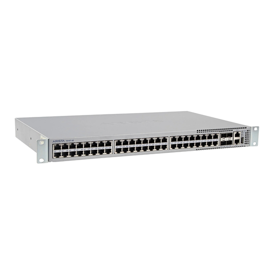
Appendix C Front Panel This appendix displays the front panel of all switches covered by this guide. Figure 17: DCS-7010T-48 and DCS-7010T-48-DC Port numbers System status LED USB port Port status LED Fan tray status LED 10 Ethernet management port SFP+ Ports Power supply 1 status 11 RJ-45 ports... -
Page 33: Appendix D: Rear Panel
Appendix D Rear Panel This appendix displays the rear panel of all switches covered by this guide. Depending on the modules installed, the rear panel on your switch may appear slightly different. Figure 19: DCS-7010T-48 Power Supply Module 1 Airflow direction indicator Airflow direction indicator label (inactive) label (active) - Page 34 Figure 21: DCS-7010T-48-DC Power supply 1 terminals Power supply 2 terminal Grounding location cover Power supply 1 terminal Power supply 2 terminals cover Figure 22: DCS-7010TX-48-DC Power supply 1 terminals Power supply 2 terminals Fan release handle Power supply 1 status Power supply 2 status Fan status LED Grounding location...
-
Page 35: Appendix E: Maintenance And Field Replacement
• The switch will shut down if the fan module is disconnected for more than a minute. • Before you begin, refer to the Arista Networks document Safety Information and Translated Safety Warnings available at: https://www.arista.com/en/support/product-documentation Removing a Fan Module The following steps are required when removing or replacing fans from a switch. -
Page 37: Appendix F: Regulatory Model Numbers
Appendix F Regulatory Model Numbers This appendix lists the Regulatory Model Numbers (RMNs) for the product models for the switches described in this document. Table 10: Regulatory Model Numbers and Product Numbers Regulatory Model Number (RMN) Product Name(s) DCS-7010T-48 DCS-7010T-48, DCS-7010T-48-DC DCS-7010TX-48 AN1738 AN1764... -
Page 39: Appendix G: Taiwan Rohs Information
Appendix G Taiwan RoHS Information This appendix provides Taiwan RoHS information for switches covered by this guide. For Taiwan BSMI RoHS Table, go to https://www.arista.com/assets/data/pdf/AristaBSMIRoHS.pdf.
Need help?
Do you have a question about the 7010 Series and is the answer not in the manual?
Questions and answers