
Related Manuals for MTS Sensors Temposonics V POWERLINK R Series


Summary of Contents for MTS Sensors Temposonics V POWERLINK R Series
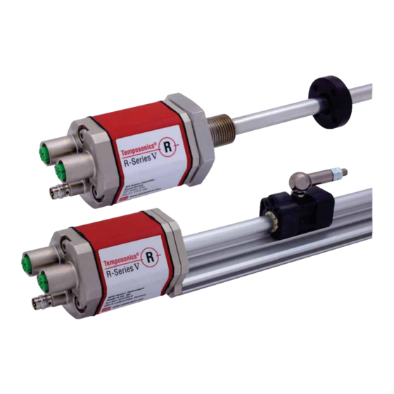
- Page 1 ® Temposonics Magnetostrictive Linear Position Sensors R-Series V POWERLINK ® Temposonics Operation Manual...
-
Page 2: Table Of Contents
R-Series V POWERLINK Temposonics ® Operation Manual Table of contents 1. Introduction ..............................3 1.1 Purpose and use of this manual ................................3 1.2 Used symbols and warnings ..................................3 2. Safety instructions ............................3 2.1 Intended use ......................................3 2.2 Foreseeable misuse .................................... -
Page 3: Introduction
This product may be used only for the applications defined under item 1 and only in conjunction with the third-party devices and components recommended or approved by MTS Sensors. As a prerequisite of proper and safe operation the product requires correct transport, storage, mounting and commissioning and must be operat ed with utmost care. -
Page 4: Installation, Commissioning And Operation
Fill the outer packaging around the sensor completely to prevent damage during transport. 2.4 Safety instructions for use in explosion-hazardous areas The sensor is not suitable for operation in explosion-hazardous areas. 2/ See also applicable MTS Sensors terms of sales and delivery on: www.mtssensors.com I 4 I... -
Page 5: Identification
R-Series V POWERLINK Temposonics ® Operation Manual 3. Identification 3.1 Order code of Temposonics ® 6 2 × M12 female connectors (5 pin), 1 × M8 male connector (4 pin) G Magnet slider backlash free (part no. 253 421), 1 Standard suitable for internal linearization Block magnet L (part no. -
Page 6: Order Code Of Temposonics
R-Series V POWERLINK Temposonics ® Operation Manual 3.2 Order code of Temposonics ® 6 2 × M12 female connectors (5 pin), 5 Rod 1 × M8 male connector (4 pin) B Base unit (only for replacement) 1 Standard stroke length: 25…5900 mm (1…232 in.) 1 POWERLINK, position and velocity (1…30 position(s)) 1 POWERLINK, position and velocity,... -
Page 7: Nameplate
R-Series V POWERLINK Temposonics ® Operation Manual 3.3 Nameplate RH5SA0080M01D561U301 Order code MAC: 00-03-CA-00-58-F6 MAC address S/N: 19020950 Serial number 12JAN2019 Date of Production Fig. 1: Example of nameplate of a R-Series V RH5 sensor with POWERLINK output 3.4 Approvals •... -
Page 8: Product Description And Commissioning
(position) variable in the fields of automated systems and mechanical engineering. Strain pulse detected by converter Principle of operation and system construction The absolute, linear position sensors provided by MTS Sensors Fig. 2: Time-of-flight based magnetostrictive position sensing principle rely on the company’s proprietary Temposonics ®... -
Page 9: Styles And Installation Of Temposonics ® Rp5
R-Series V POWERLINK Temposonics ® Operation Manual 4.2 Styles and installation of Temposonics ® RP5-M-A/-V (0.2) Sensor electronics housing Null zone Stroke length Dead zone 48 (1.89) 25…6350 66/71* (0.67) (2.28) (1.1) (1…250) (2.6/2.8*) e.g. for M5 or #10 screws Adjustable mounting clamp 35.6 (1.4) Ø... -
Page 10: Styles And Installation Of Temposonics ® Rh5
R-Series V POWERLINK Temposonics ® Operation Manual 4.3 Styles and installation of Temposonics ® RH5-M/S-A/-V – RH5 with threaded flange M18×1.5-6g or ¾"-16 UNF-3A Sensor electronics housing Null zone Stroke length Dead zone 25…7620 63.5 / 66* (0.67) (2.68) (2.01) (1…300) (2.5 / 2.6*) Threaded flange »M«: M18×1.5-6g... - Page 11 R-Series V POWERLINK Temposonics ® Operation Manual RH5-J-A/-V – RH5 with threaded flange M22×1.5-6g and Ø 12.7 mm rod Sensor electronics housing Null zone Stroke length Dead zone 25…5900 73.6 (0.67) (2.68) (2.01) (1…232) (2.9) Threaded flange »J«: M22×1.5-6g (0.98) (2.09) RH5-B-A/-V –...
- Page 12 R-Series V POWERLINK Temposonics ® Operation Manual Installation of RH5 with threaded flange In the case of threaded flange M18×1.5-6g or M22×1.5-6g, provide Fix the sensor rod via threaded flange M18×1.5-6g, M22×1.5-6g or a screw hole based on ISO 6149-1 (Fig. 11). See ISO 6149-1 for further ¾"-16 UNF-3A.
-
Page 13: Magnet Installation
R-Series V POWERLINK Temposonics ® Operation Manual Centered mounting 4.4 Magnet installation of block magnet Typical use of magnets Air gap: 3 ±2 8 ±2 (0.12 ±0.08) (0.31 ±0.08) • Rotationally symmetrical Sensor element (RH5) Block magnet • Height tolerances can be Non-magnetic mounting plate compensated, because the (RP5, RH5) - Page 14 2 × U-magnet (part no. 251 416-2). Do not fall below the minimum distance between the magnets of 75 mm (3 in.) for multi-position measurement. Contact MTS Sensors if * Stroke length > 5000 mm (196.9 in.) you need a magnet distance < 75 mm (3 in.).
-
Page 15: Alignment Of The Magnet With The Option "Internal Linearization
A sensor with internal linearization is delivered with the magnet with which the sensor was squared during production. In order to achieve the best possible result, MTS Sensors recommends to operate the sensor with the supplied magnet. For the internal linearization, the following magnets can be used: •... -
Page 16: Replacement Of Sensor
R-Series V POWERLINK Temposonics ® Operation Manual 3. Insert the new base unit. 4.6 Replacement of sensor Mount the ground lug on a screw. Tighten the screws. The base unit of the sensor model RH5 (RH5-B) is replaceable as shown in Fig. 23 and Fig. 24 for the sensor designs »M«, »S« and »T«. -
Page 17: Electrical Connection
R-Series V POWERLINK Temposonics ® Operation Manual 4.7 Electrical connection Connector wiring Connect the sensor directly to the control system, indicator or other Placement of installation and cabling have decisive influence on evaluating systems as follows: the sensor‘s electromagnetic compatibility (EMC). Hence correct installation of this active electronic system and the EMC of the entire Port 1 Port 2... -
Page 18: Frequently Ordered Accessories For Rp5 Design
R-Series V POWERLINK Temposonics ® Operation Manual 4.8 Frequently ordered accessories for RP5 design – Additional options available in our Accessories Guide 551 444 15.2 57 (2.24) (1.65) (0.6) (1.69) (0.94) (1.69) (0.55) (0.55) 49 (1.93) (0.79) (0.79) (0.79) 40 (1.57) 40 (1.57) 40 (1.57) 40 (1.57) -
Page 19: Frequently Ordered Accessories For Rh5 Design
R-Series V POWERLINK Temposonics ® Operation Manual 4.9 Frequently ordered accessories for RH5 design – Additional options available in our Accessories Guide 551 444 Ø 32.8 (Ø 1.29) Ø 4.3 Ø 32.8 Ø 30.5 Ø 25.4 (Ø 0.17) (Ø 1.29) (Ø... -
Page 20: Frequently Ordered Accessories For Powerlink Output
R-Series V POWERLINK Temposonics ® Operation Manual 4.10 Frequently ordered accessories for POWERLINK output – Additional options available in our Accessories Guide 551 444 (2.05) (1.7) ® Material: Zinc nickel-plated Material: CuZn nickel plated • Connect wirelessly via Wi-Fi enabled Material: PUR jacket;... -
Page 21: Operation
R-Series V POWERLINK Temposonics ® Operation Manual 5. Operation (when the sensor is started up, these statuses run through) 5.1 Initial start-up MS/ER The position sensor R-Series V POWERLINK transfers position NS/RN and velocity values via the POWERLINK output. POWERLINK is an Industrial Ethernet interface and is managed by the Ethernet POWERLINK Standardization Group (EPSG). -
Page 22: Topologies And Hubs
R-Series V POWERLINK Temposonics ® Operation Manual POWERLINK supports various topologies when building up a This chapter describes how to adjust the node ID of the R-Series V POWERLINK. The node ID is used to identify a device in a network. - Page 23 R-Series V POWERLINK Temposonics ® Operation Manual Connect the TempoLink smart assistant to the power supply using the Connect the USB cable with the micro USB connector to the port plug-in power supply with plug adapters. Connect the barrel connector labeled “USB”...
- Page 24 R-Series V POWERLINK Temposonics ® Operation Manual 6.1.4 Graphical User Interface (GUI) Click the menu symbol in the top left to get to the main menu: Fig. 37: Changing the node ID of the connected sensor After the node ID has been configured, click the EXIT COMMAND MODE button.
-
Page 25: Setting The Node Id Via "Automation Studio
R-Series V POWERLINK Temposonics ® Operation Manual Name Description 6.2 Setting the node ID via "Automation Studio" STATE_SEARCH_FOR_NODE This is the initial state in this project. In this state, PLC tries to read the vendor ID of The following is a description how to set the node ID of the controlled nodes starting from node ID 1 up to R-Series POWERLINK as well as the R-Series V POWERLINK using node ID 239 (all node IDs which are supposed... - Page 26 ID variable. It also sets the variable which is used to store the node ID of the first found controlled node with vendor ID from MTS Sensors to a value which is invalid for a controlled node (source code below).
- Page 27 R-Series V POWERLINK Temposonics ® Operation Manual Source Code “SdoAccessCyclic.c” /******************************************************************** * COPYRIGHT -- ******************************************************************** * Program: SdoAccess * File: SdoAccessCyclic.c * Author: SSchumacher * Created: November 18, 2014 ******************************************************************** * Implementation of program SdoAccess ********************************************************************/ #include <bur/plctypes.h> #ifdef _DEFAULT_INCLUDES #include <AsDefault.h>...
- Page 28 As shown in the screenshot of the variable watch, a controlled node with vendor ID from MTS Sensors has been found at node ID 32. The node ID has been successfully set to 1. Fig. 44: Variable watch As shown in the screenshot of the I/O mapping, the sensor is working well using its new node ID.
-
Page 29: Integration Of R-Series V Powerlink In The Control System
R-Series V POWERLINK Temposonics ® Operation Manual 7. Integration of R-Series V POWERLINK in the control system Navigate to the location where the XDD file for the R-Series V Project integration The project integration is described using an example with a B&R POWERLINK is stored. - Page 30 R-Series V POWERLINK Temposonics ® Operation Manual Adding R-Series V POWERLINK to a network As in the system designer also in the physical view on the left the In the right of the main view is the “Toolbox - Hardware Catalog”. sensor is connected to the control.
- Page 31 R-Series V POWERLINK Temposonics ® Operation Manual The available configuration data of the sensor is divided into two groups: • Channels: Measurement data of the sensor, that can be transferred cyclically. To activate cyclic transmission of a specific data item, click on the data item column called "Value"...
-
Page 32: Communication Segment
R-Series V POWERLINK Temposonics ® Operation Manual 7.2 Communication segment The parameters of the group "Channels" (available data items for cyclical transmission): Index 2302 Variable Unsigned8 Current number of magnets detected on the sensor Current power supply in mV 2303 Variable Unsigned16 Current position value of up to 30 magnets... - Page 33 R-Series V POWERLINK Temposonics ® Operation Manual The parameters of the group “Device Specific Parameters”: Index 2201 Variable Unsigned8 Setting the number of position magnets that are used simultaneously on 2202 Number of entries Variable Unsigned8 Filter type Variable Unsigned8 •...
- Page 34 R-Series V POWERLINK Temposonics ® Operation Manual Index 6010 The preset can be set for up to 30 magnets. Number of entries Variable Unsigned8 1…30 Preset for 1…30 magnets Variable Integer32 6301 Number of entries Variable Unsigned8 It can be set for up to 30 magnets. 1…30 Variable Unsigned8...
- Page 35 R-Series V POWERLINK Temposonics ® Operation Manual Index Subindex Name Object type Attribute Data type Description 6401 Work area low limit Array This object contains the position value, at which bit 2 of the according p406_work_area_state_channel in object 6400h (Working Area State Number of entries Variable Unsigned8...
-
Page 36: Maintenance And Troubleshooting
8.2 Maintenance The sensor is maintenance-free. 8.3 Repair Repairs of the sensor may be performed only by MTS Sensors or a repair facility explicitly authorized by MTS Sensors. For return see section "2.6 Return" on page 4. 8.4 List of spare parts No spare parts are available for this sensor. -
Page 37: Technical Data
R-Series V POWERLINK Temposonics ® Operation Manual 10. Technical data 10.1 Technical data Temposonics ® Output Interface Ethernet POWERLINK Data protocol POWERLINK V2 Measured value Position, velocity/option: Simultaneous multi-position and multi-velocity measurements up to 30 magnets Measurement parameters Resolution: Position 0.5…100 μm (selectable) Cycle time Stroke length... - Page 38 R-Series V POWERLINK Temposonics ® Operation Manual 10.2 Technical data Temposonics ® Interface Ethernet POWERLINK Data protocol POWERLINK V2 Measured value Position, velocity/option: Simultaneous multi-position and multi-velocity measurements up to 30 magnets Resolution: Position 0.5…100 μm (selectable) Cycle time Stroke length ≤...
- Page 39 Please include safety data sheets of the substances, if applicable. Please include safety data sheets of the substances, if applicable. consult MTS Sensors to determine measures to be taken before consult MTS Sensors to determine measures to be taken before shipment.
- Page 40 R-Series V POWERLINK Temposonics ® Operation Manual 12. Appendix II C Y L I N D E R P O R T D E T A I L S NOTES: 1. Dimensions and tolerances based on ANSI Y14.5-1982. 2. MTS has extracted all pertinent information from MS33649 to generate this document.
-
Page 41: Glossary
R-Series V POWERLINK Temposonics ® Operation Manual 13. Glossary The Managing Node, usually an industrial PC or a PLC, controls V POWERLINK, for the communication in the network as master and sets the clock for the synchronization of all devices. In a network there is only one POWERLINK network are Controlled Nodes. - Page 42 R-Series V POWERLINK Temposonics ® Operation Manual R-Series V POWERLINK supports Synchronization Mode. The syn- chronization mode enables clock-synchronous data exchange between sensor and control. The synchronous measurement is an essential requirement for motion-controlled applications. computer hardware. The properties and functions of a POWERLINK device are described XML Device D contains all relevant data that are important for the implementation of the device in the controller as well as for data exchange during...
- Page 43 MTS, Temposonics and Level Plus are registered trademarks of MTS Systems Corporation in the United States; MTS SENSORS and the MTS SENSORS logo are trademarks of MTS Systems Corporation within the United States. These trademarks may be protected in other countries. All other trademarks are the property of their respective owners. Copyright © 2020 MTS Systems Corporation. No license of any intellectual property rights is granted.
Need help?
Do you have a question about the Temposonics V POWERLINK R Series and is the answer not in the manual?
Questions and answers