Future Automation PS Series Installation Instructions Manual
Manual articulating wall mounts
Hide thumbs
Also See for PS Series:
- Product manual (24 pages) ,
- Installation instructions manual (16 pages)

Related Manuals for Future Automation PS Series


Summary of Contents for Future Automation PS Series
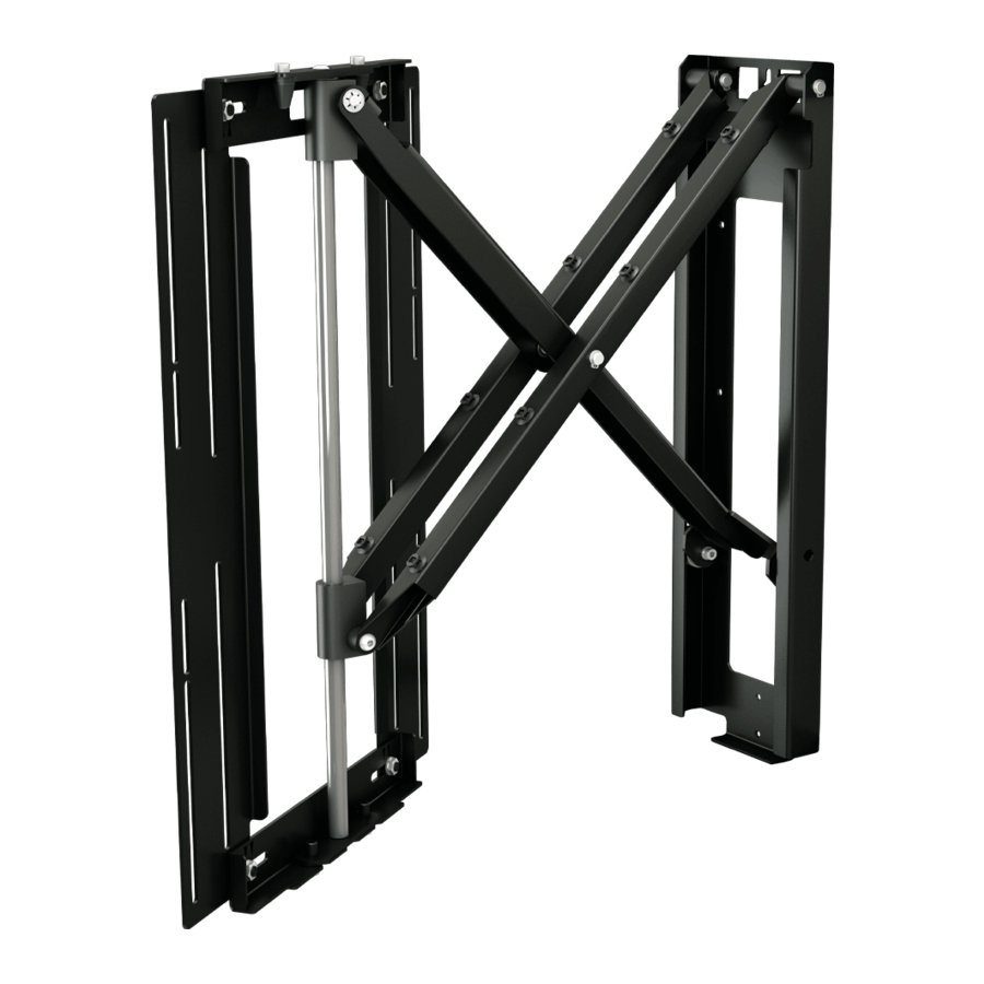
- Page 1 PS RA N GE PS3 2 , 40 , 5 5 & 6 5 M A NUAL ARTIC ULA TIN G WA LL M OUN TS IN STA L LA TIO N I NSTRUC TI ON S ISSUE 004-PF...
- Page 3 Clean only with a dry cloth and always unplug any electrical items being used in conjunction with this product before cleaning. Future Sound & Vision trading as Future Automation intend to make this and all documentation as accurate as possible. However, Future Automation makes no claim that the information contained herein covers all details, conditions or variations, nor does it provide for every possible contingency in connection with the installation or use of this product.
-
Page 4: Product Warranty
Under the warranty, Future Automation aims to either solve the issue remotely (via telephone or email support) or if the mechanism requires a part, arrange a visit to your premises by a Future Automation approved engineer or send replacement items where appropriate. -
Page 5: Gu Idec O Ntents
GU IDE C O NTENTS SAFETY DISCLA IMER PROD UCT WA RRA NTY & RISK ASSESS MENT GUID E CONTENTS PACKAGE CONTENTS VESA MOUNT A DJUSTMENTS CALCULATING M OUNTING H EIGH T D ETACHING THE SCREEN M OUN T SURFACE MOUNTING STUD RA IL M OUNTING CABLE M A NA GEMENT FITTING THE SCREEN... -
Page 6: Package Contents
PA CKAGE CON TENTS 1 - PS RANGE BRACKET 1.1 - WALL PLATE 1.2 - SCREEN MOUNT 1.3 - SCREEN MOUNT UPRIGHTS 1.4 - CABLE TIE ANCHORS PS RANGE ACCESSORY PACK: - SCREEN FIXINGS PACK (MULTI-PACK OF NUTS, BOLTS, SPACERS AND WASHERS) - PACK OF CABLE TIES... - Page 7 V ESA M OUN T A DJUSTM ENTS The PS42 and PS50 brackets are capable of mounting all screens with VESA100 to VESA 400 bolt patterns. The bracket will ship with the mount head To achieve VESA 300/ 400 patterns; Release the Screen Mount Uprights by removing the 4 x M8 nuts from rear of the uprights as shown below.
- Page 8 CAL CUL ATIN G MO UN TIN G H EIGH T Dimension X corresponding slots on the PS Bracket Screen Mount. Measure from the top of the screen, down to the top mounting hole on the Wall Plate (Dimension X as indicated above) to...
- Page 9 SCREEN MOUNT The screen mount will need to be detached from the PS Bracket before wall mounting. This is achieved by removing the 2 x M6 bolts from the underside of frame as shown (Right). Once the bolts have been removed, pull the bottom edge of the Mount Frame away from the bracket before lifting it up and away from the Wall Plate.
- Page 10 S U RF A CE MO UN TIN G plate should be located the distance of hole in Wall Plate to secure it to the wall. Dimension X (measured on page 6) down Once checking the bracket is level on from the top of the screen position.
- Page 11 S TU D RA IL KIT (OPTIONNAL) MO UN TIN G Dimension X down from the top of the screen position Fix the bracket to the Rail by screwing 2 x M6 bolts through the Rail into threaded holes in dimension to position the upper Stud Rail on the wall the Wall Plate.
-
Page 12: Cable Management
CAB LE MA NAGEMEN T Power and signal cable wall sockets should be kept outside of the footprint of the bracket to All cables should enter the bracket at the top of the Wall Plate, run down each of the outer Scissor Arms and attach to the rear of the Screen Frame as shown below. - Page 13 FITTING TH E SC REEN Lay the screen face down on a padded surface and place the Screen Mount, removed in Stage 2, onto the screens four mount holes. Secure the Screen Mount to the back of the screen, using the bolts and washers provided in the Fixings Pack as shown below. If the screen has provided in the Fixings Pack.
- Page 14 SC REEN CONT. Lift the Screen and Mount Frame up and onto the central bar of the PS Bracket, hooking it on the opposite way to its removal on page 8. Make sure the 2 locating nubbins at the top of the Secure the Screen and Mount Frame to the rest of the bracket by replacing the 2 x M6 bolts into the underside of Mount Frame.
-
Page 15: F Riction Adjustment
F RICTION ADJUSTMENT loose, the friction can be adjusted using the M8 nut and bolt arrangement on the bottom sliding collar as shown below. Loosen bolt to decrease friction, or tighten to increase friction. Bottom Sliding Collar M8 Bolt... - Page 16 EUROPEAN OFFICE Unit 6-8 Enterprise Park Brunel Road 127 Venture Drive Bedford Dover Bedfordshire MK41 9TG 03820 +44 (0) 1438 833577 +1 (603) 742 9181 info@futureautomation.co.uk info@futureautomation.net Mon - Fri 8:00 to 17:30 GMT Mon - Fri 7:00 to 17:00 EST Saturday &...
Need help?
Do you have a question about the PS Series and is the answer not in the manual?
Questions and answers