Table of Contents
Advertisement
Quick Links
Advertisement
Table of Contents

Subscribe to Our Youtube Channel
Related Manuals for Future Automation EAD3


Summary of Contents for Future Automation EAD3
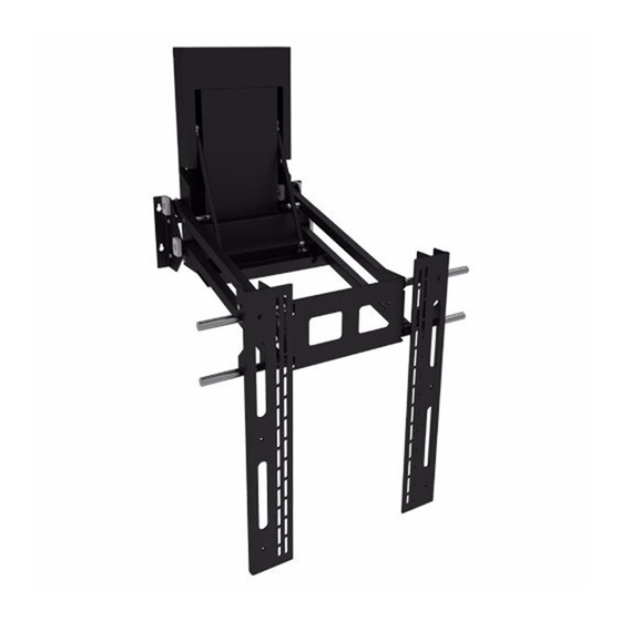
- Page 1 EAD3 Electric Advance and Drop TV Wall Mount Installation Instructions Issue 002...
-
Page 2: Safety Disclaimer
Clean only with a dry cloth and always unplug any electrical items being used in conjunction with this product before cleaning. Future Sound & Vision trading as Future Automation intend to make this and all documentation as accurate as possible. However, Future Automation makes no claim that the information contained herein covers all details, conditions or variations, nor does it provide for every possible contingency in connection with the installation or use of this product. -
Page 3: Table Of Contents
4 - Screen Position Adjustment 5 - Setting Mechanism Limits 6 - Cable Management Mechanism Control 1 - General 2 - Infrared (IR) Operation 3 - Contact Closure Operation 4 - RS232 Operation Contact Information Page 3 of 17 // Installation Instructions - EAD3... - Page 4 • Compensation for loss of use of the product, and consequential loss of any kind. Any part of your system that needs to be replaced during a warranty repair becomes the property of Future Automation. Customer Support - Contact Details...
-
Page 5: Package Contents
4.1 - x2 AAA Batteries 4.2 - Mains Power Lead 4.3 - Infra-Ref Control Lead 4.5 - CAT5 Lead with RJ45 Connector 4.6 - Screen Fixings Pack (Multi-pack of Nuts, Bolts and Washers) Page 5 of 17 // Installation Instructions - EAD3... -
Page 6: Mechanism Quick-Start Guide
Mechanism Quick-start Guide Quick-start Guide Some Future Automation mechanisms may ship with the control box disconnected to prevent damage during transit. In order to operate the mechanism, the control box will need to reconnected, then have mains power applied along with the desired control method. -
Page 7: Installation Instructions
Installation Instructions 1 - Mechanism Positioning Before mounting the EAD3 it is important to ensure there are no obstructions through the full travel of the mechanism. 1. With the mechanism laid flat, offer the screen onto the Screen Uprights and measure from the bottom of the screen to the bottom of the wall plate to determine the mechanisms position on the wall. -
Page 8: Fixing To The Wall
Mechanism Control section of the installation instructions) - other fixings are in place. Remove 8 x M5 Bolts to Release Covers and Circled Fixing Holes MUST Access Mounting Holes. Be Used. Page 8 of 17 // Installation Instructions - EAD3... -
Page 9: Screen Mounting
Uprights (1.8 - still attached to the EAD3) so the keyholes fixings on these are the same horizontal distance apart as the Mount bobbins. 3. Lift and hook the Screen onto the EAD3. The Mount Bobbins should locate into the keyholes on the Main Uprights (1.8) to secure the screen to the bracket. -
Page 10: Screen Position Adjustment
4 - Screen Position Adjustment 1. Once the screen has been attached to the EAD3, it can be adjustment horizontally by sliding the screen and Uprights left or right along the stainless steel Mount Bars shown below. The s lots in the Screen Uprights (1.4) allow for vertical position adjustment by loosening screen fixings and raising or lowering screen to the... -
Page 11: Setting Mechanism Limits
3. Once the desired OUT position has been achieved, re-tighten the 2 x M5 Nuts loosened in step 1. Wall Plate Buffers. IN Switch - This must NOT be adjusted. IN Switch Buffer OUT Limit Switch Slider. Page 11 of 17 // Installation Instructions - EAD3... -
Page 12: Cable Management
3. After entering from the Cable Cut out in the Wall Plate (1.1), cables should be routed along the underside of the Upper Arms (following the dotted line below) and fixed using cable ties secured to the tie blocks supplied. Page 12 of 17 // Installation Instructions - EAD3... -
Page 13: Mechanism Control
Replacing Mechanism Batteries The standard Future Automation Infrared (IR) remote control required x2 AAA batteries to operate. These are provided with the mechanism in the Accessories Pack. These batteries can be replaced as the per the image below. -
Page 14: Infrared (Ir) Operation
STOP - Will stop the operation of the mechanism at ANY position. IMPORTANT Only buttons indicated above are functional with the product. Any other button press will STOP the mechanism. Page 14 of 17 // Installation Instructions - EAD3... -
Page 15: Contact Closure Operation
Contact Closure LED on the printed circuit board as shown below. RJ45 Pin Layout Contact Closure LED Layout LED 1 LED 2 LED 3 LED 4 LED 5 (NOT USED) Contact Closure Input Port Contact Closure Input Table Page 15 of 17 // Installation Instructions - EAD3... -
Page 16: Rs232 Operation
Action fa_in Carriage Return (Enter / ASCII 13) Device IN fa_out Carriage Return (Enter / ASCII 13) Device OUT fa_stop Carriage Return (Enter / ASCII 13) Device STOP (At any position) Page 16 of 17 // Installation Instructions - EAD3... -
Page 17: Contact Information
Email: info@futureautomation.co.uk Email: info@futureautomation.net Office Hours: Office Hours: Mon - Fri 8:00 to 17:30 GMT Mon - Fri 7:00 to 17:00 EST Saturday & Sunday - Closed Saturday & Sunday - Closed Page 17 of 17 // Installation Instructions - EAD3...
Need help?
Do you have a question about the EAD3 and is the answer not in the manual?
Questions and answers