
Related Manuals for Vanguard Instruments LTCA-10


Summary of Contents for Vanguard Instruments LTCA-10
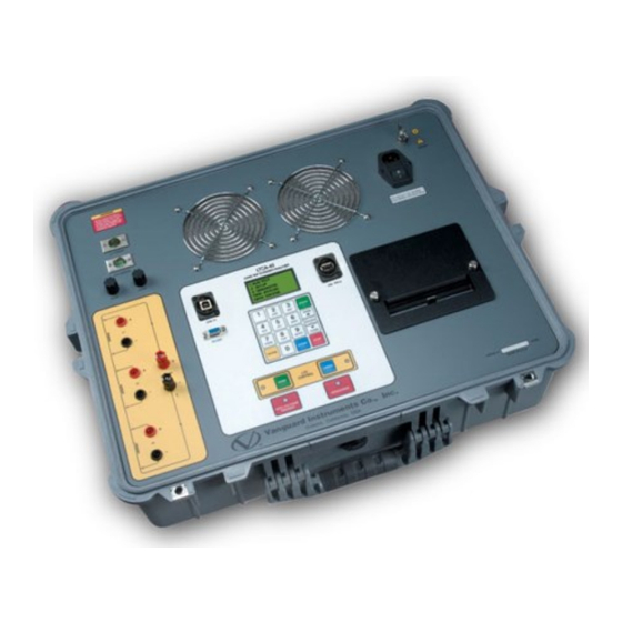
- Page 1 USER’S MANUAL for the LTCA-10™ LTCA-40™ LOAD TAP CHANGER ANALYZER Vanguard Instruments Company, Inc. 1520 S. Hellman Ave. Ontario, California 91761 TEL: (909) 923-9390 August 2015 FAX: (909) 923-9391 Rev. 2.3...
- Page 2 Any deviation from the procedures described in this User’s Manual may create one or more safety hazards, may damage the LTCA-10/40, damage the test transformer, or cause errors in the test results. Vanguard Instruments Company, Inc. assumes no liability for unsafe or improper use of the LTCA-10/40.
-
Page 3: Table Of Contents
TECHNICAL SPECIFICATIONS ..................8 LTCA-10 Technical Specifications .................. 8 LTCA-40 Technical Specifications .................. 9 CONTROLS AND INDICATORS..................10 LTCA-10 Controls and Indicators .................. 10 LTCA-40 Controls and Indicators .................. 12 PRE-TEST SETUP ......................14 Operating Voltages ......................14 LTCA-10/40 LCD Contrast Control ................14 LTCA-10/40 Printer Paper Control ................ - Page 4 Figure 2.0 LTCA-40 Controls and Indicators ................12 Figure 3.0 Typical Connections to a Load Tap Changer (LTC) ........... 15 Figure 4.0 Typical LTCA-10/40 Connection Diagram (Dynamic Resistance Test) ....16 Figure 6.0 Typical LTCA-40 Connection Diagram (2 Windings) ..........17 Figure 7.0 Typical LTCA-40 Connection Diagram (3 Windings) ..........
-
Page 5: Conventions Used In This Document
TCA-10/LT TCA-40 US ER’S MAN CONV VENTIO ONS USE ED IN T THIS DO OCUME This docu ument uses t the followin g convention KEY] • A key y or switch o on the LTCA A-10/40 is in ndicated as •... -
Page 6: Introduction
LCD screen. A special current source allows the LTCA-10 to output 1, 5 and 10 Amperes of test current. The LTCA-40 can output 1, 5, 10 or 40 Amperes of test current. For added safety, the current source... -
Page 7: Furnished Accessories
Furnished Accessories The LTCA-10/40 is furnished with eight 50-foot test cables with “quick disconnect” type test plugs on the unit end and battery-type clamps at the test load end. One power cord, one ground cable, one current sense cable, one LTC operation cable and a cable-carrying bag is also included. -
Page 8: Technical Specifications
TCA-10/LT TCA-40 US ER’S MAN TECHNICA AL SPEC CIFICATIO LTCA-10 Te echnical Sp pecificatio Table 1.0 LTC CA-10 Speci fications Load tap cha anger analyzer TYPE 21”W x 9” H x x 17”D (53 cm x 24 cm x 43 c cm);... -
Page 9: Ltca-40 Technical Specifications
TCA-10/LT TCA-40 US ER’S MAN LTCA-40 Te echnical Sp pecificatio Table 2.0 LTC CA-40 Speci fications Load tap cha anger analyzer TYPE 25”W x 8.5”H H x 20”D (63.5 c cm x 21.6 cm x x 50 cm); Weig ght: 46 lbs (20 k HYSICAL SPEC CIFICATIONS 100 –... -
Page 10: Controls And Indicators
CONTROLS AND INDICATORS LTCA-10 Controls and Indicators The LTCA-10’s controls and indicators are shown in Figure 1.0 below. A leader line with an index number points to each control and indicator, which is cross-referenced to a functional description in Table 3.0. The table describes the function of each item on the control-panel. The purpose of the controls and indicators may seem obvious, but users should become familiar with them before using the LTCA-10/40. -
Page 11: Table 3.0 Functional Descriptions Of Ltca-10 Controls And Indicators
LTCA-10/LTCA-40 USER’S MANUAL Table 3.0 Functional Descriptions of LTCA-10 Controls and Indicators Item Panel Markings Functional Description Number AC Current Clamp-on AC current probe connector USB Interface Port Flash Drive USB Flash Drive Interface Port None Air Vents 120-240 7.5A, 50-60... -
Page 12: Ltca-40 Controls And Indicators
LTCA-10/40. Accidental misuse of the controls will usually cause no serious harm. Users should also be familiar with the safety summary found on the front page of this User’s Manual. -
Page 13: Table 4.0 Functional Descriptions Of Ltca-40 Controls And Indicators
LTCA-10/LTCA-40 USER’S MANUAL Table 4.0 Functional Descriptions of LTCA-40 Controls and Indicators Item Panel Markings Functional Description Number AC Current Clamp-on AC current probe connector USB Interface port The air intake cooling fans maintain the internal temperature. There are output... -
Page 14: Pre-Test Setup
LTCA-10/40 Printer Paper The LTCA-10/40’s built-in thermal printer uses 4.5-inch wide thermal paper for printing test results. To maintain the highest print quality and to avoid paper jams, the use of thermal paper supplied by Vanguard Instruments Company is highly recommended. Additional paper can be ordered from the following sources: Vanguard Instruments Co, Inc. -
Page 15: Operating Procedures
LTCA-10/LTCA-40 USER’S MANUAL OPERATING PROCEDURES The LTCA-10/40 is simple to operate and only requires the selection of choices from display menus and responding to displayed prompts. However, first-time operators should review the following operating procedures to become familiar with all LTCA-10/40 operations and the logical branching for various test options. -
Page 16: Cable Connections
TCA-10/LT TCA-40 US ER’S MAN Cable Conn nections Do no ot touch or disconnect any test lea ad that is con nnected to a transformer termi inal while hi gh current is s being cond ducted durin ng a test. Fai ilure to heed d this warni... -
Page 17: Figure 6.0 Typical Ltca-40 Connection Diagram (2 Windings)
LTCA-10/LTCA-40 USER’S MANUAL Figure 5.0 Typical LTCA-40 Connection Diagram (2 Windings) -
Page 18: Figure 7.0 Typical Ltca-40 Connection Diagram (3 Windings)
LTCA-10/LTCA-40 USER’S MANUAL Figure 6.0 Typical LTCA-40 Connection Diagram (3 Windings) -
Page 19: General Procedures
TCA-10/LT TCA-40 US ER’S MAN General Pro ocedures a. G Ground the L LTCA-10/40 to substatio n ground (It tem 6 in Figu ure 1.0, Item m 5 in figure 2.0). Always conn nect the LTC CA-10/40 to the substatio... -
Page 20: Performing A Resistance Test
LTCA-10/LTCA-40 USER’S MANUAL Performing a Resistance Test a. Start from the “START-UP” menu: 1. TEST XFMR 03/04/09 2. SETUP 09:28:03 3. USER DIAG Press the key (TEST XFMR) to start a test. b. The following menu will be displayed: 1. RESISTANCE TEST 2. - Page 21 TCA-10/LT TCA-40 US ER’S MAN Press the key to se elect copper as the windi ing material. . Continue t step f. Press the key to se elect aluminu um as the wi inding mater rial. Continu ue to step f. Press the key to m manually ente...
- Page 22 TCA-10/LT TCA-40 US ER’S MAN e LTCA-10/ /40 will calcu ulate the equ uivalent resi stance value e at this new mperature. NOTE h. T The following g “WARNIN NG” screen w will be displ layed: ******** **WARNIN G******* DANGE...
- Page 23 S ction 6.1 for instructions on how to s select this op ption. NOTE j. T The LTCA-10 0/40 determ ines when th he resistance e reading is s stable and di isplays the esistance val lues on the L...
- Page 24 (YES) to print the test results on the built-in thermal printer. The last test results displayed on the LCD screen will be printed. Typical LTCA-10/40 test reports are shown in Figure 7.0, Figure 8.0, and Figure 9.0. Continue to step 2.
- Page 25 EVIOUS DA ATA IN BU /01/09 10:30 APPEND P REV DATA CLEAR PR EV DATA The L LTCA-10/40 retains the c current test r results in its working me emory. When test is finished, th e user can ap ppend the ne...
- Page 26 TCA-10/LT TCA-40 US ER’S MAN 1. YES If you u wish to sav ve the record d, press the key (YES S) and contin nue to step p 2. NO If you u do not wish h to save the e record, pres ss the ey (NO).
-
Page 27: Resistance Test Result Printouts
LTCA-10/LTCA-40 USER’S MANUAL 5.4.1. Resistance Test Result Printouts Figure 7.0 Typical Triple Reading Test Report Printout Figure 8.0 Typical Dual Reading Test Report Printout... -
Page 28: Figure 10.0 Typical Single Reading Test Report Printout
LTCA-10/LTCA-40 USER’S MANUAL Figure 9.0 Typical Single Reading Test Report Printout... -
Page 29: Performing A Special Resistance Test
The “ENTER SPECIAL TEST TIME MINUTES” screen will be displayed: ENTER SPECIAL TEST TIME MINUTES (1-45): Enter the test time (between 1-45 minutes) using the keypad on the LTCA-10/40 and then press the [ENTER] key. Ten (10) minutes is used for the test time in this example. - Page 30 LTCA-10/LTCA-40 USER’S MANUAL 1. YES If you wish to convert readings to standard temperature, press the key (YES). The “WINDING MATERIAL” menu will be displayed: WINDING MATERIAL 1. COPPER, Tk=234.5 2. ALUMINUM, Tk=225.0 3. MANUALLY ENTER Tk a. Press the key to select copper as the winding material.
- Page 31 NTER] Reference Te emperature. P Press the y to confirm t the temperat ture selection e LTCA-10/ /40 will calcu ulate the equ uivalent resi stance value e at this new mperature. NOTE i. T The following g “WARNIN...
- Page 32 S ction 6.1 for instructions on how to s select this op ption. NOTE k. T The LTCA-10 0/40 determ ines when th he resistance e reading is s stable and sh hows the esistance val lue on the LC...
- Page 33 TCA-10/LT TCA-40 US ER’S MAN e test record d must be sav ved to Flash EEPROM s so that it can be recalled prin nted at a late er time. NOTE 1. YES If you u wish to sav ve the record d, press the key (YES S) and contin...
-
Page 34: Special Resistance Test Result Printout
LTCA-10/LTCA-40 USER’S MANUAL 5.5.1. Special Resistance Test Result Printout Figure 10.0 Typical Single Reading Test Report Printout... -
Page 35: Performing A Dynamic Ltc Test
Select the shot time by pressing the corresponding key on the LTCA-10/40’s keypad , or d. The “SELECT TEST CURRENT” menu will be displayed as shown below. The LTCA- 10 offers a selection of 5 or 10 Amps while the LTCA-10 offers a selection of 10 or 40 AMPS. SELECT TEST CURRENT: SELECT TEST CURRENT: 1. - Page 36 The LTCA-10/40 determines when the resistance reading is stable and displays the “READY TO CAPTURE DATA” screen: READY TO CAPTURE DATA PRESS “ENTER”...
- Page 37 LTCA-10/LTCA-40 USER’S MANUAL Press the [ENTER] key to start capturing data for the time period selected in step e. The LTC must be manually started to begin switching through the taps. [LTC RAISE] If the LTC cable is connected, then pressing the...
- Page 38 LTCA-10/LTCA-40 USER’S MANUAL i. The “PRINT AN EXPANSION PLOT” menu will be displayed: PRINT AN EXPANSION PLOT? 1. YES 2. NO 1. YES An expansion plot graphs the resistance waveform in more detail by allowing the selection of a timeframe to be plotted using an appropriate resistance scale. Press key (YES) to print an expansion plot.
- Page 39 TCA-10/LT TCA-40 US ER’S MAN j. T The “SAVE T THIS RECO ORD?” menu u will be disp played: SAVE THI IS RECORD 1. YES 2. NO e test record d must be sav ved to Flash EEPROM s so that it can be recalled prin nted at a late...
-
Page 40: Dynamic Ltc Test Result Printouts
LTCA-10/LTCA-40 USER’S MANUAL 5.6.1. Dynamic LTC Test Result Printouts Figure 11.0 Sample Normal Dynamic LTC Test Plot... -
Page 41: Figure 13.0 Sample Dynamic Ltc Test Expansion Plot
LTCA-10/LTCA-40 USER’S MANUAL Figure 12.0 Sample Dynamic LTC Test Expansion Plot... -
Page 42: Diagnostic Mode
In diagnostic mode, the LTCA-10/40 can run a resistance test, display the sense voltages, and test current on the LTCA. This feature can be used to verify the LTCA-10/40’s voltage and current readings against an external meter. Use the steps below to initiate a diagnostic test. - Page 43 LTCA-10/LTCA-40 USER’S MANUAL e. The V1, V2, and V3 test currents will be displayed as shown below: V1 = 07.53mV V2 = 08.23mV V3 = 09.12mV = 01.091A Press the [STOP] key to end the diagnostic test and return to the “START-UP” menu.
-
Page 44: Setup Menu
TCA-10/LT TCA-40 US ER’S MAN Setup Menu The setup p menu is us sed to config gure the LTC CA-10/40 an nd to also rec call and print t stored test records. T This section n outlines the e procedures for accessin ng and using g the Setup M... - Page 45 LTCA-10/LTCA-40 USER’S MANUAL d. The “STATION” screen will be displayed: STATION: ↑/↓ TO POSITION “ENTER TO ACCEPT” Enter the station name by using the LTCA-10/40’s alpha-numeric keypad, and then press [ENTER] key. e. The “CIRCUIT” screen will be displayed: CIRCUIT: ↑/↓...
- Page 46 The “OPERATOR” screen will be displayed: OPERATOR: ↑/↓ TO POSITION “ENTER TO ACCEPT” Enter the name of the operator by using the LTCA-10/40’s alpha-numeric keypad, and [ENTER] then press the key. You will be returned to the “START-UP” menu.
-
Page 47: Restoring A Test Record
LTCA-10/LTCA-40 USER’S MANUAL 5.8.2. Restoring a Test Record Use the following steps to restore a test record from the LTCA-10/40’s Flash EEPROM to the unit’s working memory. a. Start from the “START-UP” menu: 1. TEST XFMR 03/04/09 2. SETUP 09:28:03 3. - Page 48 LTCA-10/LTCA-40 USER’S MANUAL 2. SCROLL TO SELECT Press the key if you want to scroll through the LTCA-10/40’s record directory to find the record number. The “RECORDS DIRECTORY” screen will be displayed: RECORDS DIRECTORY “UP” TO SCROLL FWD “DWN” TO SCROLL RVS Press the [PAPER ∧...
-
Page 49: Figure 14.0 Typical Test Record Printout
LTCA-10/LTCA-40 USER’S MANUAL Figure 13.0 Typical Test Record Printout... -
Page 50: Printing The Test-Record Directory
LTCA-10/LTCA-40 USER’S MANUAL 5.8.3. Printing the Test-Record Directory A directory of all the test records stored in the LTCA-10/40’s Flash EEPROM can be printed on the thermal printer using the steps below. a. Start from the “START-UP” menu: 1. TEST XFMR 03/04/09 2. -
Page 51: Figure 15.0 Typical Record Directory Printout
LTCA-10/LTCA-40 USER’S MANUAL Figure 14.0 Typical Record Directory Printout... -
Page 52: Erasing A Test Record
LTCA-10/LTCA-40 USER’S MANUAL 5.8.4. Erasing a Test Record Follow the steps below to erase a single test record or the entire directory of test records from the LTCA-10/40’s Flash EEPROM. a. Start from the “START-UP” menu: 1. TEST XFMR 03/04/09 2. - Page 53 2. ERASE ALL RECORDS Press the key (ERASE ALL RECORDS) to erase all records stored in the LTCA-10/40’s memory. The following confirmation screen will be displayed: ERASE ALL RECORDS! ARE YOU SURE? “ENTER” TO CONTINUE...
-
Page 54: Enabling The Computer Interface
EEPROM to a PC via the RS-232C or USB port. To use this mode, first run the provided PC software and then connect the PC to the RS-232C or USB port on the LTCA-10/40. The software will automatically make the connection to the LTCA-10/40. -
Page 55: Setting The Date And Time
LTCA-10/LTCA-40 USER’S MANUAL 5.8.6. Setting the Date and Time a. Start from the “START-UP” menu: 1. TEST XFMR 03/04/09 2. SETUP 09:28:03 3. USER DIAG Press the key (SETUP). b. The following menu will be displayed: 1. ENTER XFMR ID 2. -
Page 56: Setting The Test Value Display Font
LTCA-10/LTCA-40 USER’S MANUAL 5.8.7. Setting the Test Value Display Font The font used to display test values on the screen can be made bold for better visibility. This only affects the test values displayed during testing and does not affect any other text such as menu items. -
Page 57: Ltca-10/40 Special Features
The LTCA-10/40 has a built-in 3 minute minimum delay between the start of the test and when the resistance value is displayed on the LCD. This feature eliminates the possibility of early erroneous readings. - Page 58 LTCA-10/LTCA-40 USER’S MANUAL 1520 S. Hellman Ave • Ontario, CA 91761 • USA Phone: 909-923-9390 • Fax: 909-923-9391 www.vanguard-instruments.com LTCA-10/40™ User’s Manual • Version 2.3 • August 24, 2015 Copyright © 2015 by Vanguard Instruments Company, Inc.
Need help?
Do you have a question about the LTCA-10 and is the answer not in the manual?
Questions and answers