Table of Contents

Subscribe to Our Youtube Channel
Related Manuals for Vanguard Instruments ATRT-01 S3


Summary of Contents for Vanguard Instruments ATRT-01 S3
- Page 1 ATRT-01 S3 and ATRT-01B S3 SINGLE PHASE TRANSFORMER TURNS-RATIO METERS USER’S MANUAL Vanguard Instruments Company, Inc. 1520 S. Hellman Ave. Ontario, California 91761, USA TEL: (909) 923-9390 May 2011 FAX: (909) 923-9391 Revision 1...
- Page 2 ATRT-01/01B S3 USER’S MANUAL REV 1 SAFETY SUMMARY This manual applies to both the ATRT-01 S3 and ATRT-01B S3 current transformer turns-ratio meters. The operating procedures are virtually the same for both models, and any differences are clearly described where applicable.
-
Page 3: Table Of Contents
CONVENTIONS USED IN THIS DOCUMENT ..................1 INTRODUCTION ........................2 General Description and Features ................... 2 Technical Specifications ....................4 1.2.1. ATRT-01 S3 Technical Specifications ................ 4 1.2.2. ATRT-01B S3 Technical Specifications ..............5 1.2.3. Controls and Indicators .................... 6 PRE-TEST SETUP ........................ - Page 4 Table 1. ATRT-01 S3 Technical Specifications ................. 4 Table 2. ATRT-01B S3 Technical Specifications ................5 Table 3. Functional Descriptions of ATRT-01 S3 Controls and Indicators ........7 Table 4. Functional Descriptions of ATRT-01B S3 Controls and Indicators ........8 LIST OF FIGURES Figure 1.
-
Page 5: Conventions Used In This Document
CONVENTIONS USED IN THIS DOCUMENT This document uses the following conventions: • The general term “ATRT” is used in this manual to refer to the ATRT-01 S3 and ATRT-01B S3. [KEY], [SWITCH], [KNOB] • A key, switch, or knob on the ATRT is indicated as •... -
Page 6: Introduction
LCD screen. User Interface The ATRT-01 S3 features a back-lit LCD screen (128 x 64 pixels) that is viewable in direct sunlight and low-light levels. A rugged 16-key membrane keypad is used to enter test information and to operate the unit. - Page 7 REV 1 ATRT-01/01B S3 USER’S MANUAL Battery Power for Exceptional Portability The ATRT-01B S3 is powered by a 6-volt, 7 ampere-hour, lead acid battery. This high capacity battery, coupled with the ATRT-01B S3’s low power consuming circuitry, allows the unit to be used continuously for up to 4 hours per charge.
-
Page 8: Technical Specifications
ATRT-01/01B S3 USER’S MANUAL REV 1 Technical Specifications 1.2.1. ATRT-01 S3 Technical Specifications Table 1. ATRT-01 S3 Technical Specifications TYPE Transformer Turns Ratio Tester PHYSICAL SPECIFICATIONS Dimensions: 12” x 10” x 8” (30.4 cm x 25.4 cm x 20.3 cm) Weight: 8 lbs (3.6 Kg) -
Page 9: Atrt-01B S3 Technical Specifications
REV 1 ATRT-01/01B S3 USER’S MANUAL 1.2.2. ATRT-01B S3 Technical Specifications Table 2. ATRT-01B S3 Technical Specifications TYPE Transformer Turns Ratio Tester PHYSICAL SPECIFICATIONS Dimensions: 12” x 10” x 8” (30.4 cm x 25.4 cm x 20.3 cm) Weight: 9 lbs (4.3 Kg) INPUT POWER 90 to 240 Vac, 50/60 Hz Battery: SLA battery delivering up to 4 hours of continuous operation per charge. -
Page 10: Controls And Indicators
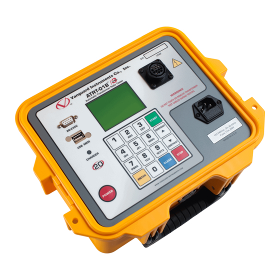
REV 1 1.2.3. Controls and Indicators The ATRT-01 S3 and ATRT-01B S3 controls and indicators are shown in Figure 1 and Figure 2, respectively. A leader line with an index number points to each control and indicator, which is cross-referenced to a functional description in the corresponding table. The purpose of the controls and indicators may seem obvious, but users should familiarize themselves with them before using the ATRT. -
Page 11: Table 3. Functional Descriptions Of Atrt-01 S3 Controls And Indicators
REV 1 ATRT-01/01B S3 USER’S MANUAL Figure 1. ATRT-01 S3 Controls and Indicators Table 3. Functional Descriptions of ATRT-01 S3 Controls and Indicators Item Panel Markings Functional Description Number USB MEM USB Flash drive interface RS-232C RS-232C computer interface port... -
Page 12: Table 4. Functional Descriptions Of Atrt-01B S3 Controls And Indicators
ATRT-01/01B S3 USER’S MANUAL REV 1 Figure 2. ATRT-01B S3 Controls and Indicators Table 4. Functional Descriptions of ATRT-01B S3 Controls and Indicators Item Panel Markings Functional Description Number USB MEM USB Flash drive interface RS-232C RS-232C computer interface port Back-lit LCD screen (128 x 64 pixels), viewable in bright sunlight and low light levels H and X lead connector (16-pin male). -
Page 13: Pre-Test Setup
PRE-TEST SETUP ATRT-01 S3 Operating Voltage The ATRT-01 S3 can be operated from 120 Vac or 240 Vac. The power voltage can be set using the voltage selector switch on the front panel (see Figure 1, item #5) ATRT-01B S3 Operating Power The ATRT-01B S3 is powered by a rechargeable (6 Vdc / 7 AH) sealed lead acid gel battery. -
Page 14: Operating Procedures
ATRT-01/01B S3 USER’S MANUAL REV 1 OPERATING PROCEDURES ATRT Transformer Connection Diagrams Figure 3. Typical Single-Phase Transformer Connection... -
Page 15: Figure 4. Typical Auto Transformer Connection
REV 1 ATRT-01/01B S3 USER’S MANUAL Figure 4. Typical Auto Transformer Connection... -
Page 16: Figure 5. Typical Ct Connection
ATRT-01/01B S3 USER’S MANUAL REV 1 Figure 5. Typical CT Connection... -
Page 17: Figure 6. Typical Bushing Ct Connection On A Single Transformer
REV 1 ATRT-01/01B S3 USER’S MANUAL Figure 6. Typical Bushing CT Connection on a Single Transformer... -
Page 18: Setting The Test Voltage
14:21:34 time: 14:21:34 date: 05/24/11 date: 05/24/11 ATRT-01 S3 “START-UP” menu ATRT-01B S3 “START-UP” menu Press the key (SETUP). b. The following screen will be displayed: 1. RECORD ID 1. RECORD ID 2. TEST VOLTAGE 2. TEST VOLTAGE 3. - Page 19 REV 1 ATRT-01/01B S3 USER’S MANUAL d. The voltage will be set and the following confirmation message will be displayed: 40 VOLTS SET Press any key to return to the “START-UP” menu.
-
Page 20: Setting The Date And Time
ATRT-01/01B S3 USER’S MANUAL REV 1 Setting the Date and Time To set the date and time: a. Start from the “START-UP” menu: 1. TEST TRANSFORMER 2. SETUP 3. CALCULATOR time: 14:21:34 date: 05/24/11 Press the key (SETUP). b. The following screen will be displayed: 1. -
Page 21: Setting The Interface Language
REV 1 ATRT-01/01B S3 USER’S MANUAL Setting the Interface Language Follow the steps below to set the interface language (English, Spanish, or Turkish): a. Start from the “START-UP” menu: 1. TEST TRANSFORMER 2. SETUP 3. CALCULATOR time: 14:21:34 date: 05/24/11 Press the key (SETUP). -
Page 22: Setting The Frequency (Atrt-01B S3 Only)
ATRT-01/01B S3 USER’S MANUAL REV 1 Setting the Frequency (ATRT-01B S3 Only) Follow the steps below to set the preferred frequency (50 or 60 Hz): a. Start from the “START-UP” menu: 1. TEST TRANSFORMER 2. SETUP 3. CALCULATOR bAT: time: 14:21:34 date: 05/24/11... -
Page 23: Performing Tests
REV 1 ATRT-01/01B S3 USER’S MANUAL Performing Tests 3.6.1. Entering Test Record Header Information You can enter the test record header information before performing tests. The record header includes identifying information such as the company, station, circuit, manufacturer, etc. Once the header information has been set, it will apply to all subsequent test records. - Page 24 ATRT-01/01B S3 USER’S MANUAL REV 1 d. The following screen will be displayed: STATION: ↑ ↓ TO POSITION "ENTER" TO ACCEPT [ENTER] Type the station name using the alpha-numeric keypad and then press the key. e. The following screen will be displayed: CIRCUIT: ↑...
- Page 25 REV 1 ATRT-01/01B S3 USER’S MANUAL g. The following screen will be displayed: MODEL: ↑ ↓ TO POSITION "ENTER" TO ACCEPT Type the transformer’s model information using the alpha-numeric keypad and then [ENTER] press the key. h. The following screen will be displayed: SERIAL NUMBER: ↑...
- Page 26 ATRT-01/01B S3 USER’S MANUAL REV 1 j. The following screen will be displayed: OPERATOR: ↑ ↓ TO POSITION "ENTER" TO ACCEPT [ENTER] Type the operator’s name using the alpha-numeric keypad and then press the key. All header information will be saved, and you will be returned to the “START-UP” menu.
-
Page 27: Testing A Single Phase Transformer
REV 1 ATRT-01/01B S3 USER’S MANUAL 3.6.2. Testing a Single Phase Transformer Follow the steps below to test a single phase transformer: a. Start from the “START-UP” menu: 1. TEST TRANSFORMER 2. SETUP 3. CALCULATOR time: 14:21:34 date: 05/24/11 Press the key (TEST TRANSFORMER). - Page 28 ATRT-01/01B S3 USER’S MANUAL REV 1 NAME PLATE VOLTAGE: H : X Type the H winding name plate voltage value using the numeric keypad. The screen will be updated as shown: NAME PLATE VOLTAGE: H : X 500 : [ENTER] Press the key.
- Page 29 REV 1 ATRT-01/01B S3 USER’S MANUAL d. The following screen will be displayed: "START" TO TEST "STOP" TO ABORT [START] Press the key to start the test. e. The following screen will be displayed while the test is being performed: TESTING AT 40 VOLTS TEST IN PROGRESS PLEASE WAIT...
- Page 30 ATRT-01/01B S3 USER’S MANUAL REV 1 f. The following screen will be displayed: KEEP THIS READING? 1. YES 2. NO Press the key (YES) to save the reading. g. The following screen will be displayed: TEST SAVED Press any key to continue. The above screen will be displayed if there is currently no data in the unit’s memory buffer.
- Page 31 REV 1 ATRT-01/01B S3 USER’S MANUAL h. The following screen will be displayed: RUN ANOTHER TEST? 1. YES 2. NO 3. REPEAT PREV. TEST Press the key (NO). i. The following screen will be displayed: SAVE THIS RECORD? 1. YES 2.
-
Page 32: Testing A Three Phase Transformer
ATRT-01/01B S3 USER’S MANUAL REV 1 3.6.3. Testing a Three Phase Transformer Follow the steps below to test a three phase transformer: a. Start from the “START-UP” menu: 1. TEST TRANSFORMER 2. SETUP 3. CALCULATOR time: 14:21:34 date: 05/24/11 Press the key (TEST TRANSFORMER). - Page 33 REV 1 ATRT-01/01B S3 USER’S MANUAL d. The following screen will be displayed: 1. DY1 2. DY3 3. DY5 4. DY7 5. DY9 6. DY11 Select the transformer configuration by pressing the corresponding key ( ). For this example, press the key (Dy1).
- Page 34 ATRT-01/01B S3 USER’S MANUAL REV 1 NAME PLATE VOLTAGE: H : X 500 : 0 Type the X winding name plate voltage value using the numeric keypad. The screen will be updated as shown: NAME PLATE VOLTAGE: H : X 500 : 10 [ENTER] Press the...
- Page 35 REV 1 ATRT-01/01B S3 USER’S MANUAL [START] Make the cable connections per the instructions and then press the key to run the Phase A test. g. The following screen will be displayed while the test is being performed: TESTING: DYN1 phase a The Phase A test results will be displayed on the LCD screen when testing has finished: %DIFF RATIO...
- Page 36 ATRT-01/01B S3 USER’S MANUAL REV 1 %DIFF RATIO +15.003 0.02 +15.015 0.10 "ENTER" TO CONTINUE.. Line 1 of the results shows the Phase A test results, and line 2 shows the Phase B test results. [ENTER] Press the key to continue. j.
- Page 37 REV 1 ATRT-01/01B S3 USER’S MANUAL l. The following screen will be displayed: KEEP THIS READING? 1. YES 2. NO Press the key (YES) to save the reading. m. The following screen will be displayed: TEST SAVED Press any key to continue. The above screen will be displayed if there is currently no data in the unit’s memory buffer.
- Page 38 ATRT-01/01B S3 USER’S MANUAL REV 1 n. The following screen will be displayed: RUN ANOTHER TEST? 1. YES 2. NO 3. REPEAT PREV. TEST Press the key (NO). o. The following screen will be displayed: SAVE THIS RECORD? 1. YES 2.
-
Page 39: Working With Test Records
REV 1 ATRT-01/01B S3 USER’S MANUAL Working With Test Records 3.7.1. Viewing the Contents of the Working Memory Whenever a test is performed or a test record is retrieved, the data is stored in the ATRT’s working memory. You can view the test data using the steps below: a. -
Page 40: Saving Test Results To A Test Record
ATRT-01/01B S3 USER’S MANUAL REV 1 3.7.2. Saving Test Results to a Test Record After performing a test, the user is presented the option to save the test results to the unit’s Flash EEPROM or to a USB Flash Drive. If the test results are not saved immediately after performing a test, they will still remain in the working memory and can be saved later, as long as a new test has not been performed and the unit has not been turned off. - Page 41 REV 1 ATRT-01/01B S3 USER’S MANUAL If a USB Flash drive is connected to the unit, continue to step d. If a USB Flash drive is NOT connected to the unit, continue to step e. d. The following screen will be displayed: 1.
-
Page 42: Restoring A Test Record From Flash Eeprom
ATRT-01/01B S3 USER’S MANUAL REV 1 3.7.3. Restoring a Test Record From Flash EEPROM Use the steps below to restore a test record from the ATRT’s Flash EEPROM to the working memory: a. Start from the “START-UP” menu: 1. TEST TRANSFORMER 2. - Page 43 REV 1 ATRT-01/01B S3 USER’S MANUAL d. The following screen will be displayed: RESTORE RECORD 1.ENTER RECORD NUMBER 2.SCROLL TO SELECT If you have a USB Flash drive inserted in the ATRT’s “USB MEM” port, the following screen will be displayed instead of the above screen: NOTE 1.INTERNAL STORAGE 2.THUMB DRIVE...
- Page 44 ATRT-01/01B S3 USER’S MANUAL REV 1 1.2. The following screen will be displayed: RECORD RESTORED! DISPLAY RECORD? 1.YES 2.NO Press the key (YES) to display the test record. 1.3. The basic information about the restored test record will be displayed as shown: SINGLE PHASE Num Tests: 1...
- Page 45 REV 1 ATRT-01/01B S3 USER’S MANUAL [Contrast ∧] [Contrast ∨] Press the button or the key to display the next or previous test record, respectively. The basic test record information will be displayed as shown: 05/25/11 09:52 SINGLE PHASE 1 TESTS When you have located the test record that you would like to restored, [ENTER] press the...
-
Page 46: Restoring A Test Record From A Usb Flash Drive
ATRT-01/01B S3 USER’S MANUAL REV 1 3.7.4. Restoring a Test Record From a USB Flash Drive Use the steps below to restore a test record from a USB Flash drive to the ATRT’s working memory: a. Make sure the USB Flash drive containing the test record(s) is inserted in the ATRT’s USB Flash drive port (“USB MEM”... - Page 47 REV 1 ATRT-01/01B S3 USER’S MANUAL d. The following screen will be displayed: 1.INTERNAL STORAGE 2.THUMB DRIVE Press the key (THUMB DRIVE). e. The following screen will be displayed: RESTORE THUMB DRIVE REC_ Type the record number that you would like to restore using the alpha-numeric keypad [ENTER] and then press the key.
- Page 48 ATRT-01/01B S3 USER’S MANUAL REV 1 [Contrast ∨] Press the key. The test record details will be displayed as shown below: 1 SINGLE PHASE 40 volts %DIFF RATIO 1.003 0002 [STOP] Press the key to return to the “START-UP” menu. The restored test record will remain loaded in the working memory.
-
Page 49: Copying Test Records To A Usb Flash Drive
REV 1 ATRT-01/01B S3 USER’S MANUAL 3.7.5. Copying Test Records to a USB Flash Drive Use the steps below to copy one or all test records from the unit’s Flash EEPROM to a connected USB Flash drive: a. Make sure a USB Flash drive is connected to the unit’s “USB MEM” port, and then start from the “START-UP”... - Page 50 ATRT-01/01B S3 USER’S MANUAL REV 1 d. The following screen will be displayed: COPY REC TO THUMB DRV 1.COPY SINGLE RECORD 2.COPY ALL RECORDS 1. COPY SINGLE RECORD Press the key (COPY SINGLE RECORD) to copy a single test record from the ATRT’s Flash EEPROM to the connected USB Flash drive.
- Page 51 REV 1 ATRT-01/01B S3 USER’S MANUAL 2. COPY ALL RECORDS Press the key (COPY ALL RECORDS) to copy all test records from the ATRT’s Flash EEPROM to the connected USB Flash drive. All test records will be copied from the unit to the connected USB Flash drive. The following screen will be displayed when the process is finished: ALL RECORDS HAVE BEEN TRANSFERRED TO THUMB...
-
Page 52: Viewing The Test Record Directory
ATRT-01/01B S3 USER’S MANUAL REV 1 3.7.6. Viewing the Test Record Directory Use the steps below to browse through a directory of the test records stored in the ATRT’s Flash EEPROM memory: a. Start from the “START-UP” menu: 1. TEST TRANSFORMER 2. - Page 53 REV 1 ATRT-01/01B S3 USER’S MANUAL d. The following screen will be displayed: RECORDS DIRECTORY "UP" TO SCROLL FWD "DWN" TO SCROLL RVS [Contrast ∧] [Contrast ∨] Press the key to scroll through the test record directory. The test record header will be displayed as shown: SINGLE PHASE Num Tests: 1 05/27/11...
-
Page 54: Erasing Test Records From The Flash Eeprom
ATRT-01/01B S3 USER’S MANUAL REV 1 3.7.7. Erasing Test Records from the Flash EEPROM Follow the steps below to erase test records from the Flash EEPROM a. Start from the “START-UP” menu: 1. TEST TRANSFORMER 2. SETUP 3. CALCULATOR time: 14:21:34 date: 05/24/11... - Page 55 REV 1 ATRT-01/01B S3 USER’S MANUAL d. The following screen will be displayed: ERASE RECORD 1.ERASE SINGLE REC. 2.ERASE ALL RECORDS "STOP" TO EXIT If you have a USB Flash drive inserted in the ATRT’s “USB MEM” port, the following screen will be displayed instead of the above screen: NOTE 1.ERASE INTERNAL REC 2.ERASE THUMB DRV REC...
- Page 56 ATRT-01/01B S3 USER’S MANUAL REV 1 ERASE RECORD NUMBER: You can cancel the process and return to the “START-UP” menu by [STOP] pressing the key. NOTE Type the record number that you would like to erase using the alpha-numeric [ENTER] keypad and then press the key.
- Page 57 REV 1 ATRT-01/01B S3 USER’S MANUAL 2. SCROLL TO SELECT Press the key (SCROLL TO SELECT) to scroll through the test record directory and locate the test record that you would like to erase. The following screen will be displayed: RECORDS DIRECTORY "UP"...
- Page 58 ATRT-01/01B S3 USER’S MANUAL REV 1 2. ERASE ALL RECORDS Press the key (ERASE ALL RECORDS) to erase all the test records from the unit’s internal Flash EEPROM. The following warning screen will be displayed: ERASE ALL RECORDS! ARE YOU SURE? "ENTER"...
-
Page 59: Erasing Test Records From A Usb Flash Drive
REV 1 ATRT-01/01B S3 USER’S MANUAL 3.7.8. Erasing Test Records from a USB Flash Drive Follow the steps below to erase test records from a USB Flash drive: a. Make sure a USB Flash drive is connected to the unit’s “USB MEM” port, and then start from the “START-UP”... - Page 60 ATRT-01/01B S3 USER’S MANUAL REV 1 e. The following screen will be displayed: ERASE RECORD 1.ERASE SINGLE REC. 2.ERASE ALL RECORDS "STOP" TO EXIT 1. ERASE SINGLE REC. Press the key (ERASE SINGLE REC.) to erase a single test record from the connected USB Flash drive.
- Page 61 REV 1 ATRT-01/01B S3 USER’S MANUAL [STOP] Press the key if you do not want to erase all the test records. You will be returned to the “START-UP” menu. [ENTER] Press the key to proceed with deleting all the test records from the connected USB Flash drive.
-
Page 62: Using The Turns Ratio Calculator
ATRT-01/01B S3 USER’S MANUAL REV 1 Using the Turns Ratio Calculator The ATRT-01 and ATRT-01B S2 feature a turns ratio calculator that can be used to calculate the turns ratio for various transformer types. The user only needs to provide the H and X name plate voltage values and the unit will calculate the turns ratio. - Page 63 REV 1 ATRT-01/01B S3 USER’S MANUAL c. The following screen will be displayed: H0 accessible? 1. YES 2. NO 1. YES Press the key (YES) if H0 is accessible. The following screen will be displayed: 1. YND1 2. YND3 3. YND5 4.
- Page 64 ATRT-01/01B S3 USER’S MANUAL REV 1 d. The following screen will be displayed NAME PLATE VOLTAGE: H : X Type the H name plate voltage value using the keypad. The screen will be updated: NAME PLATE VOLTAGE: H : X 1,734 : [ENTER] Press the...
-
Page 65: Appendix A - Transformer Vector Group Codes
REV 1 ATRT-01/01B S3 USER’S MANUAL APPENDIX A – TRANSFORMER VECTOR GROUP CODES Utility power transformers manufactured in accordance with IEC specifications have a Rating Plate attached in a visible location. This plate contains a list of the transformer's configuration and operating specifications. -
Page 66: Appendix B - Common Ansi Transformer Descriptions
ATRT-01/01B S3 USER’S MANUAL REV 1 APPENDIX B – Common ANSI Transformer Descriptions... - Page 67 REV 1 ATRT-01/01B S3 USER’S MANUAL...
- Page 68 ATRT-01/01B S3 USER’S MANUAL REV 1...
- Page 69 REV 1 ATRT-01/01B S3 USER’S MANUAL...
- Page 70 ATRT-01/01B S3 USER’S MANUAL REV 1...
- Page 71 REV 1 ATRT-01/01B S3 USER’S MANUAL...
- Page 72 ATRT-01/01B S3 USER’S MANUAL REV 1...
- Page 73 REV 1 ATRT-01/01B S3 USER’S MANUAL...
-
Page 74: Appendix C - Cei/Iec 60076-1 Transformer Descriptions
ATRT-01/01B S3 USER’S MANUAL REV 1 APPENDIX C – CEI/IEC 60076-1 Transformer Descriptions... - Page 75 REV 1 ATRT-01/01B S3 USER’S MANUAL...
- Page 76 ATRT-01/01B S3 USER’S MANUAL REV 1...
- Page 77 REV 1 ATRT-01/01B S3 USER’S MANUAL...
- Page 78 ATRT-01/01B S3 USER’S MANUAL REV 1...
- Page 79 REV 1 ATRT-01/01B S3 USER’S MANUAL...
- Page 80 ATRT-01/01B S3 USER’S MANUAL REV 1...
-
Page 81: Appendix D - Australian Std.2374 Transformer Descriptions
REV 1 ATRT-01/01B S3 USER’S MANUAL APPENDIX D – Australian Std.2374 Transformer Descriptions... - Page 82 ATRT-01/01B S3 USER’S MANUAL REV 1...
- Page 83 REV 1 ATRT-01/01B S3 USER’S MANUAL...
- Page 84 ATRT-01/01B S3 USER’S MANUAL REV 1...
- Page 85 REV 1 ATRT-01/01B S3 USER’S MANUAL...
- Page 86 ATRT-01/01B S3 USER’S MANUAL REV 1...
- Page 87 REV 1 ATRT-01/01B S3 USER’S MANUAL...
- Page 88 1520 S. Hellman Ave • Ontario, CA 91761 • USA Phone: 909-923-9390 • Fax: 909-923-9391 www.vanguard-instruments.com Copyright © 2011 by Vanguard Instruments Company, Inc. ATRT-01/01B S3 User’s Manual • Revision 1.0 • May 31, 2011 • TA...
Need help?
Do you have a question about the ATRT-01 S3 and is the answer not in the manual?
Questions and answers