
Subscribe to Our Youtube Channel
Related Manuals for Vanguard Instruments WRM-10P


Summary of Contents for Vanguard Instruments WRM-10P
- Page 1 OPERATING INSTRUCTIONS for the WRM-10P™ WRM-40™ TRANSFORMER-WINDING RESISTANCE METER Vanguard Instruments Company 1710 Grevillea Court Ontario, California 91761 TEL: (909) 923-9390 Oct 2002 FAX: (909) 923-9391 Rev 1...
- Page 3 Any deviation from the procedures described in the operator’ s manual may create one or more safety hazards, damage the WRM-10P/40, the test transformer or cause errors in the test results; Vanguard Instruments Co., Inc. assumes no liability for unsafe or improper use of the WRM- 10P/40.
-
Page 4: Table Of Contents
1.3 FURNISHED ACCESSORIES..................4 2.0 WRM-10P/40 SPECIFICATIONS ..................5 3.0 CONTROLS and INDICATORS ..................6 4.0 PRETEST SETUP......................11 4.1 OPERATING VOLTAGES...................11 4.2 WRM-10P/40 LCD CONTRAST CONTROL ...............12 4.3 WRM-10P/40 PRINTER PAPER CONTROL ...............12 5.0 WRM-10P/40 PRINTER PAPER..................12 6.0 OPERATING PROCEDURES..................14 6.1 WRM-10P/40 CABLE CONNECTION ................14 6.2 GENERAL PROCEDURES..................19... - Page 5 WRM-10P/WRM-40 OPERATING INSTRUCTIONS Table of Figures Figure 1.0 WRM-10P Controls and Indicators ................6 Figure 2.0 WRM-40 Controls and Indicators ................9 Figure 3.0 90 to 130Vac Jumper Setting .................11 Figure 4.0 210 to 240Vac Jumper Setting ................12 Figure 5.0 WRM-10P/40 Menu Summary ................13 Figure 6.0 Typical WRM-10P Connection Diagram ...............14...
-
Page 6: Introduction
WRM-10P/WRM-40 OPERATING INSTRUCTIONS 1.0 INTRODUCTION 1.2 Functional Description 1.1 General Description The WRM-10P/40’ s operation is based on Vanguard Instruments Company’ s WRM- the electrical relationships described by 10P and WRM-40 are microprocessor- Ohm’ s law: R=V/I, where I is a known controlled winding resistance meters. -
Page 7: Wrm-10P/40 Specifications
Operating: 0°C to 55°C; Storage: -40°C to 65°C WARRANTY One-year parts & labor (post warranty service is available) NOTE: THE ABOVE SPECIFICATIONS ARE VALID AT NOMINAL OPERATING VOLTAGE AND AT A TEMPERATURE OF 25? C (77? F) WRM-10P/40? SPECIFICATIONS MAY BE UPGRADED AND CHANGED WITHOUT PRIOR NOTICE. -
Page 8: Controls And Indicators
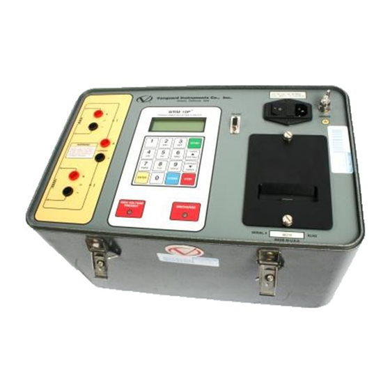
WRM-10P/WRM-40 OPERATING INSTRUCTIONS 3.0 CONTROLS AND INDICATORS control-panel. The purpose of the controls WRM-10P controls and indicators are and indicators may seem obvious, but users shown in Figure 1.0. WRM-40 controls and should become familiar with them before indicators are shown in Figure 2.0. A leader using the WRM-10P/40. - Page 9 WRM-10P/WRM-40 OPERATING INSTRUCTIONS Table 2.0 Functional Descriptions of WRM-10P Controls and Indicators Fig. 1 Panel Markings Functional Descriptions Index Voltage sensing input channel #1. Female test connector jacks for connecting voltage-sensing test leads. Current output. Female test connector jacks for connecting current test leads.
- Page 10 WRM-10P/WRM-40 OPERATING INSTRUCTIONS Table 2.0 Functional Descriptions of WRM-10P Controls and Indicators Con’ t Fig. 1 Panel Markings Functional Descriptions Index Red LED indicator light. When lit, this indicator warns operators that there is a HIGH VOLTAGE possibility that voltage exists across test leads.
-
Page 11: Figure 2.0 Wrm-40 Controls And Indicators
WRM-10P/WRM-40 OPERATING INSTRUCTIONS Figure 2.0 WRM-40 Controls and Indicators... - Page 12 WRM-10P/WRM-40 OPERATING INSTRUCTIONS Table 3.0 Functional Descriptions of WRM-40 Controls and Indicators Fig. 2 Functional Descriptions Panel Markings Index Voltage sensing input channel #1. Female test connector jacks for connecting voltage-sensing test leads. Current output. Female test connector jacks for connecting current test leads.
-
Page 13: Pretest Setup
4.0 PRETEST SETUP 4.1 Operating Voltages by the placement of jumpers on the power The WRM-10P/40 operating voltages are terminal block as listed in Table 4.0 below selectable between 90-130Vac, 50/60Hz or and Figures 3.0 and 4.0 200-240, 50/60Hz. Voltage selection is set Table 4.0... -
Page 14: Wrm-10P/40 Lcd Contrast Control
Fax: 909-923-9391 Part Number: VIC TP-3 paper 4.3 WRM-10P/40 Printer Paper Control BG Instrument Co. To advance the WRM-10P/40 printer paper, press and release the “Paper ? Contrast” 13607 E. Trent Avenue Spokane, WA 99216 switch. Tel: 509-893-9881 To retract the WRM-10P/40 printer paper, press and release the “Paper ? Contrast”... -
Page 15: Figure 5.0 Wrm-10P/40 Menu Summary
WRM-10P/WRM-40 OPERATING INSTRUCTIONS Figure 5.0 WRM-10P/40 Menu Summary... -
Page 16: Operating Procedures
WRM-10P/WRM-40 OPERATING INSTRUCTIONS 6.0 OPERATING PROCEDURES WRM-10P/40 operation and the logical Before using the WRM-10P/40 for branching for various test options. More measuring any resistance, operators should experienced operators may use this figure as review the WRM-10P/40 Menu Summary a handy help and reference guide. - Page 17 WRM-10P/WRM-40 OPERATING INSTRUCTIONS...
- Page 18 WRM-10P/WRM-40 OPERATING INSTRUCTIONS...
- Page 19 WRM-10P/WRM-40 OPERATING INSTRUCTIONS...
-
Page 20: Figure 7.0 Typical Wrm-40 Connection Diagram
WRM-10P/WRM-40 OPERATING INSTRUCTIONS Figure 7.0 Typical WRM-40 Connection Diagram WARNING Always disconnect test clips from transformer bushing after discharge slowly to prevent any accidental flash-over. -
Page 21: General Procedures
Failure to follow this procedure may 2. V1 ONLY TEST damage the WRM-10P/40. b. Plug the WRM-10P/40 power cable into a b. Press key #1 to use V1 and V2 test (dual power outlet. resistance test). Press key #2 to use only V1 test (single resistance test). - Page 22 2. NO If the user selects to keep only the new test results, go to step n. i. Press key #1 to print test results. Typical WRM-10P/40 test report is shown in figure 8.0 and Figure 9.0.
- Page 23 Select key #2 will only save the current HAS BEEN SAVED ! test results in the working buffer. RUN ANOTHER TEST message is show below. Note THE WRM-10P/40 will assign a test record RUN ANOTHER TEST? number and display on the LCD. 1. YES 2. NO r.
-
Page 24: Figure 8.0 Typical Dual Reading Test Report Printout
WRM-10P/WRM-40 OPERATING INSTRUCTIONS Figure 8.0 Typical Dual Reading Test Report Printout Figure 9.0 Typical Single Reading Test Report Printout... -
Page 25: Setup Menu
Test identification data are entered When all the characters are selected with the WRM-10P/40 keypad. The (identifying the station), press the ENTER keypad has 10 keys that are alpha- key and go to the next step. The CIRCUIT... -
Page 26: Restore A Test Record
6.4.2 Restore a Test Record MODEL: This procedure allows the user to restore a test record from the WRM-10P/40’ s Flash EEPROM to working memory. The user can then review the test record using the REVIEW RECORD command (6.4.3) or print the test results on the thermal printer. -
Page 27: Review A Test Record
The above display confirms to the operator This procedure describes steps to review a that the selected record has been restored. test record residing in the WRM-10P/40? Continue on to step i. working memory. The user can view the record on the LCD screen or from a thermal f. -
Page 28: Printing Test-Record Directory
6.4.4 Printing Test-Record Directory The user can list all test records stored in the WRM-10P/40 FLASH EEPROM on to the RECORD “ID” INFO: thermal printer by using the following steps: a. Press key #2 (SETUP) on the Start-Up Menu. -
Page 29: Erase A Test Record
6.4.5 Erase a Test Record Erasing a test record begins by pressing key 1. ENTER XFMR ID #2 from the Start-Up menu. This display on 2. PREVIEW RECORD the right is now shown on the WRM-10P/40 3. RESTORE RECORD LCD: 4. NEXT PAGE... -
Page 30: Enabling Computer Interface
RS-232C port. below: An IBM PC program is provided with each WRM-10P/40 allowing the user with a PC to retrieve these test records. a. These procedural steps begin by pressing RECORD NUMBER XX key #2 (SETUP) on the Start-Up Menu. The... -
Page 31: Setting Date And Time
The date and time set begins by pressing switch generates large reactive voltage key #2 from the Start-Up menu. The display spikes that are hazardous and exceed below is now shown on the WRM-10P/40 the switch’ s voltage ratings, thus LCD: causing irreparable damage. - Page 32 2. SET TIME 3. VOLTAGE REG. TEST NO TRANSIENT DETECTED! If a switch break is detected, an advisory c. Connect WRM-10P/40 output to the message will display (shown below). Press regulating tap-switch input. Press key #3 STOP to end the voltage-regulator test.
- Page 33 WRM-10P/WRM-40 OPERATING INSTRUCTIONS...
- Page 35 1710 Grevillea Court, Ontario, CA 91761, USA Phone: 909-923-9390 Fax: 909-923-9391 Website: http//www.vanguard-instruments.com WRM-10P/40? 10/10/02: OAK...
Need help?
Do you have a question about the WRM-10P and is the answer not in the manual?
Questions and answers