
Subscribe to Our Youtube Channel
Related Manuals for Vanguard Instruments Auto-Ohm 10


Summary of Contents for Vanguard Instruments Auto-Ohm 10
- Page 1 Auto-Ohm 10 Low Resistance Micro-Ohmmeter USER’S MANUAL Vanguard Instruments Company, Inc. 1520 S. Hellman Ave. Ontario, California 91761, USA TEL: (909) 923-9390 May 16, 2017 FAX: (909) 923-9391 Revision 1.0...
-
Page 3: Safety Summary
Auto-Ohm 10. The following safety precautions must be observed during all phases of test setup, test hookups, testing, and test lead disconnection. SAFETY WARNINGS AND CAUTIONS The Auto-Ohm 10 shall be used only by trained operators. All circuit breakers under test shall be off-line and fully isolated. SERVICE AND REPAIR •... -
Page 4: Table Of Contents
Figure 3. Optional 10A Rated Hand Probe (P/N 8000-0225) ............4 Figure 4. Optional 5A Rated Hand Probe (P/N 8000-0226) ............4 Figure 5. Auto-Ohm 10 Controls and Indicators ................6 Figure 6. Battery Fuse in Protective Plastic Box ................7 Figure 7. -
Page 5: Conventions Used In This Document
REV 1.0 Auto-Ohm m 10 USER’S MANUAL CONVENT TIONS US SED IN TH HIS DOCU UMENT This docu ument uses the followin ng conventio ons: [KEY Y], [SWITC CH], [KNOB • A key y, switch, or knob on the e Auto-Ohm 10 is indicat ted as •... -
Page 6: Introduction
The Auto-Ohm 10 features a rotary knob that is used to select either the “Contact Resistance” or “Transformer Resistance” test mode. The unit's back-lit LCD screen (128 x 64 pixels) is viewable in both direct sunlight and low light level. -
Page 7: Figure 1. Included Cable Set With Alligator Clamps (P/N 8000-0231)
REV 1.0 Auto-Ohm 10 USER’S MANUAL Cables and Accessories The Auto-Ohm 10 is furnished with a 15 ft (4.57m) cable set with alligator clamps (P/N 8000- 0231). The test current and voltage sense cables are isolated on the alligator clamps. With this feature, only a single connection is needed to the device under test. -
Page 8: Figure 3. Optional 10A Rated Hand Probe (P/N 8000-0225)
Auto-Ohm 10 USER’S MANUAL REV 1.0 Figure 3. Optional 10A Rated Hand Probe (P/N 8000-0225) Figure 4. Optional 5A Rated Hand Probe (P/N 8000-0226) -
Page 9: Technical Specifications
REV 1.0 Auto-Ohm m 10 USER’S MANUAL Technical S Specificatio Table 1 . Auto-Ohm 10 Technica al Specificatio TYPE Low Resistan nce Micro-Ohm mmeter PHYSICAL 14" W x 8" H x 12" D (36 cm m x 19.4 m x 30 0.4 cm);... -
Page 10: Auto-Ohm 10 Controls And Indicators
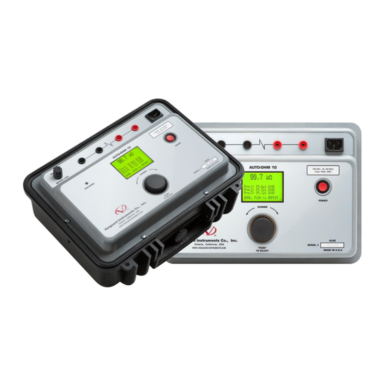
Auto-Ohm 10 USER’S MANUAL REV 1.0 Auto-Ohm 10 Controls and Indicators The Auto-Ohm 10’s controls and indicators are shown in Figure 5. The purpose of the controls and indicators may seem obvious, but users should familiarize themselves with them before using the Auto-Ohm 10. -
Page 11: Pre-Test Setup
REV 1.0 Auto-Ohm m 10 USER’S MANUAL PRE-TEST S SETUP 1.4.1. O Operating V Voltages The Auto o-Ohm 10 op perates on vo oltages betw ween 100-24 40 Vac, 50/6 60 Hz. 1.4.2. In nstalling th he Battery Fuse The Li-ion n battery ins side the Aut oOhm-10 co... -
Page 12: Replacement Rechargeable Batteries
Pressing the button exits Charging mode and enables the unit to be used normally. All Auto-Ohm 10 functions are available on either AC or Battery power. The unit will also operate on AC power with a completely discharged battery. [POWER]... -
Page 13: Adjusting Lcd Screen Contrast
REV 1.0 Auto-Ohm 10 USER’S MANUAL 1.4.5. Adjusting LCD Screen Contrast Follow the steps below to adjust the screen contrast: a. Start from the "START-UP" menu: CONT RES XFMR RES SETUP 100% [CONTROL KNOB] Turn the clock-wise until "SETUP" is highlighted, and then press [CONTROL KNOB] b. -
Page 14: Configuring Power Saving Options
Auto-Ohm 10 USER’S MANUAL REV 1.0 1.4.6. Configuring Power Saving Options The Auto-Ohm 10 offers power saving options to help conserve battery power. Follow the steps below to configure the power saving options: a. Start from the "START-UP" menu: CONT RES... - Page 15 3. When the preferred backlight turn off time is displayed, press the KNOB] Configuring Power Off Options The Auto-Ohm 10 can turn off the power after a preset time if no activity is detected. To change the preset time: [CONTROL KNOB] 1.
- Page 16 Auto-Ohm 10 USER’S MANUAL REV 1.0 Configuring Power Off Warning Time Options The Auto-Ohm 10 will display a power turn off warning after a preset time if no activity is detected. To change the preset time: [CONTROL KNOB] 1. Turn the clock-wise until "Pwr Off Warn"...
-
Page 17: Viewing Previous Test Results
REV 1.0 Auto-Ohm m 10 USER’S MANUAL 1.4.7. V Viewing Pre evious Tes st Results Follow th he steps belo ow to view t the test resu ults from the e last six test ts performed a. St tart from th e "START-UP P"... -
Page 18: Operating Procedures
Auto-Ohm 10 USER’S MANUAL REV 1.0 OPERATING PROCEDURES Connection Diagram Figure 8. Typical Auto-Ohm 10 Connection Diagram... -
Page 19: Contact Resistance Tests
REV 1.0 Auto-Ohm m 10 USER’S MANUAL Contact Re sistance T Tests The Auto o-Ohm 10's c contact resis stance test m mode allows the user to configure th he paramete for up to three tests that can the en be used t o quickly pe rform tests. - Page 20 Auto-Ohm 10 USER’S MANUAL REV 1.0 c. The following screen will be displayed: TIME DIR AUT -Empty- -Empty- (Sel Test Current) PUSH = Run Test The first test parameter, the test current, will start blinking (shown in BOLD above). To...
- Page 21 (AutoLead Detect Y/N) PUSH = Run Test The "AutoLead Detect" mode option will be selected. In this mode, the Auto-Ohm 10 will start a test once a user applies the test leads to the device under test. If you would...
-
Page 22: Performing A Contact Resistance Test
Auto-Ohm 10 USER’S MANUAL REV 1.0 2.2.2. Performing a Contact Resistance Test Follow the steps below to perform a contact resistance test: a. Start from the “START-UP” menu: CONT RES XFMR RES SETUP 100% [CONTROL The "CONT RES" option should be highlighted, but if it is not, turn the... - Page 23 REV 1.0 Auto-Ohm m 10 USER’S MANUAL he initial res sistance read ding is displa ayed at the t top of the sc creen along w with the ela psed est time at t he bottom o of the screen n.
-
Page 24: Performing A Transformer Winding Resistance Test
Auto-Ohm 10 USER’S MANUAL REV 1.0 Performing a Transformer Winding Resistance Test In "Transformer Resistance" test mode, the Auto-Ohm 10 can measure the winding resistance of transformers, electric motors, and generators. At the end of a winding resistance test, the Auto-Ohm 10 automatically dissipates the stored energy in the transformer. - Page 25 REV 1.0 Auto-Ohm m 10 USER’S MANUAL me. The nex xt three lines s display the e last three t test results. When the re eading is sta ble, ONTROL K KNOB] ress the d. T he following g screen will be displaye .57 m mΩ...
-
Page 26: Upgrading Firmware
Auto-Ohm 10 USER’S MANUAL REV 1.0 Upgrading Firmware The Auto-Ohm 10's firmware is user-upgradeable. The firmware version is displayed during the start-up sequence when the unit is powered on: Follow the steps below to download and install the latest Auto-Ohm 10 firmware: a. - Page 27 WinZip, 7-Zip, etc.). Once extracted, you should see the file "aohm10.hex". This is the firmware file. e. Copy the file "aohm10.hex" to the root folder of a USB Flash drive. f. Remove the 6 screws from the Auto-Ohm 10 front panel and lift the front panel out of the base:...
- Page 28 Insert the USB Flash drive you prepared in step "e" into the Auto-Ohm 10's USB Flash drive port. i. Flip the Auto-Ohm 10 over again and reseat in the base, but do not insert the screws. [CONTROL KNOB] [POWER] j.
- Page 29 Once the upgrade is complete, turn off the unit by holding down the button for two seconds. n. Remove the flash drive from the Auto-Ohm 10's USB Flash drive. o. Re-seat the Auto-Ohm 10 front panel in the base and re-screw the 6 screws removed in step "f".
-
Page 30: Troubleshooting Guide
Auto-Ohm 10 USER’S MANUAL REV 1.0 Troubleshooting Guide Displayed Message Explanation Probable cause Solution (for Error/Fault messages only) AC PWR… Unit operating on AC power. Battery charged to BAT… Unit operating on Battery power. Battery charged to CHARGING Unit is in charging mode. - Page 31 REV 1.0 Auto-Ohm 10 USER’S MANUAL BAT% DATA LOST… Bat GasGauge controller Battery fuse was A full charge to 100% CHARGE NOW, Est: xx% data has been lost. removed at some point. clears this Bat % shown is then only a rough estimate.
- Page 32 1520 S. Hellman Ave • Ontario, CA 91761 • USA Phone: 909-923-9390 • Fax: 909-923-9391 www.vanguard-instruments.com Copyright © 2017 by Vanguard Instruments Company, Inc. Auto-Ohm 10 User’s Manual • Revision 1.0 • May 16, 2017 • TA...
Need help?
Do you have a question about the Auto-Ohm 10 and is the answer not in the manual?
Questions and answers