
Subscribe to Our Youtube Channel
Related Manuals for Vanguard Instruments DigiTMR S2


Summary of Contents for Vanguard Instruments DigiTMR S2
- Page 1 DigiTMR S2 DIGITAL CIRCUIT BREAKER ANALYZER USER’S MANUAL Vanguard Instruments Company, Inc. 1520 S. Hellman Ave. Ontario, California 91761, USA TEL: (909) 923-9390 July 2012 FAX: (909) 923-9391 Revision 1...
- Page 2 SAFETY WARNING AND CAUTIONS The DigiTMR S2 shall be used only by trained operators. When using the DigiTMR S2 in Time- versus-Travel mode, all circuit breakers under test shall be off-line and fully isolated.
-
Page 3: Table Of Contents
Printer Paper Control ....................... 8 Printer Paper ........................8 OPERATING PROCEDURES ....................10 Configuring the VCBA S2 Software for use with the DigiTMR S2 ........10 Connecting the DigiTMR S2 to a PC via Bluetooth ............12 DigiTMR S2 Cable Connections ..................20 3.3.1. - Page 4 Table 2. Descriptions of Tabulated Test Results Elements ............68 LIST OF FIGURES Figure 1. DigiTMR S2 Controls and Indicators ................7 Figure 2. Contact Cable Connections .................... 20 Figure 3. DC Trip and DC Close Initiate Circuit Cable Connections ..........21 Figure 4.
- Page 5 APPENDIX Appendix A. ITE Circuit Breaker Model 14.4K Timing Chart ............107 Appendix B. DigiTMR S2 Test Plan for ITE Circuit Breaker Model 14.4K ........108 Appendix C. DigiTMR S2 Timing Chart for ITE Circuit Breaker Model 14.4K ......109 Appendix D.
-
Page 6: Conventions Used In This Document
CONVENTIONS USED IN THIS DOCUMENT This document uses the following conventions: [KEY] • A key or switch on the DigiTMR S2 is indicated as • Menu options are referenced as (MENU OPTION). • Screen and menu names are referenced as “SCREEN/MENU NAME”. -
Page 7: Introduction
Internal Test Record and Test Plan Storage The DigiTMR S2 can store up to 200 test records and 100 circuit breaker test plans in Flash EEPROM. A test plan comprises of all circuit breaker performance specifications (Stroke, Velocity, and Contact Time). - Page 8 A/B switch. Circuit Breaker Initiate Feature A built-in solid-state initiate device is used to operate the circuit breaker from the DigiTMR S2. Operational modes include Open, Close, Open-Close, Close-Open, and Open-Close-Open. Multiple operations such as Open-Close, Close-Open, and Open-Close-Open can be initiated using a programmable delay or by sensing the circuit breaker’s contact condition.
- Page 9 Vanguard's Windows®- based Circuit Breaker Analyzer application is included with each DigiTMR S2. The software can be used to control the unit, review test records, and create circuit breaker test plans. Test records can be exported to PDF, Excel, and XML format. All future software updates can be downloaded from the Vanguard web site at no additional charge.
-
Page 10: Operational Modes
1.2.2. Time-versus-Travel Circuit Breaker Analyzer Mode In Time-versus-Travel mode, the DigiTMR S2 applies a test voltage of 35 Vdc to each of the contact channels, thus allowing an analog to digital converter (A/D) to determine a close, open, or an insertion resistor as the state of the contact. The DigiTMR S2 records into memory 20,000 readings (in on second) from the A/D’s and the transducer position counters. -
Page 11: Technical Specifications
Furnished with full set of test leads (including 20-foot contact leads and 30-foot contact lead extensions) OPTIONS transportation case (available for the DIGITMR S2 and travel transducers) WARRANTY One year on parts and labor The above specifications are valid at nominal operating voltage and at a temperature of 25°C (77°F). -
Page 12: Digitmr S2 Controls And Indicators
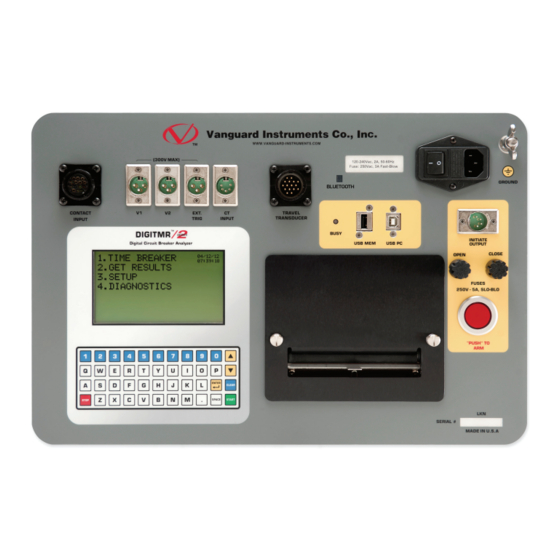
REV 1 DigiTMR S2 Controls and Indicators The DigiTMR S2’s controls and indicators are shown in Figure 1 below. The purpose of the controls and indicators may seem obvious, but users should become familiar with them before using the DigiTMR S2. Accidental misuse of the controls will usually cause no serious harm. -
Page 13: Pre-Test Setup
Printer Paper The DigiTMR S2’s built-in thermal printer uses 4.5-inch wide thermal paper for printing test results. To maintain the highest print quality and to avoid paper jams, the use of thermal paper supplied by Vanguard Instruments Company is highly recommended. Additional paper can be ordered from the following sources: Vanguard Instruments Co, Inc. - Page 14 DIGITMR S2 USER’S MANUAL REV 1 Replacing the Thermal Printer Paper The roll of thermal paper is housed inside a dispenser underneath the printer cover. To replace the paper, follow the steps below: • Unscrew the two large printer cover screws and remove the printer cover.
-
Page 15: Operating Procedures
Install the VCBA S2 software (please see the VCBA S2 software user’s manual for details) b. Connect the DigiTMR S2 to the PC by connecting a USB cable from an open USB port on the PC to the unit’s “USB PC” port. - Page 16 Make sure that the “Enable USB” option is UN-checked. Then, from the “Port” drop- down menu, select the COM port that corresponds to the port that the DigiTMR S2 is connected to. Then click the OK button. The VCBA S2 software will now recognize the...
-
Page 17: Connecting The Digitmr S2 To A Pc Via Bluetooth
The DigiTMR S2 can also be connected wirelessly to a PC using Bluetooth. To connect the unit via Bluetooth, it must first be paired with the PC. Follow the steps below to pair the DigiTMR S2 to a PC via Bluetooth: For Windows XP: a. - Page 18 Type the word “default” (without the quotes and in all lower-case) and then click on the “Next” button. e. The following window will be displayed with the option to connect to the DigiTMR S2 as a serial port: Make sure to check the box next to “AT Serial” and then click on the “Next” button.
- Page 19 Note the port number listed under the device name. In the above case, the port number is COM14. Follow the directions in section Error! Reference source not found. to configure the VCBA S2 software to connect to the DigiTMR S2 using this COM port.
- Page 20 REV 1 For Windows 7: a. Make sure the DigiTMR S2 is turned on. Then double click on the Bluetooth system tray icon (on the bottom right corner of your computer screen): b. The “Bluetooth Devices” window will be displayed:...
- Page 21 DIGITMR S2 USER’S MANUAL c. All nearby Bluetooth devices will be listed: The DigiTMR S2 will be listed as “DigiTmr S/N” where S/N is the device’s serial number. Click on the icon for the DigiTMR and then click on the “Next” button.
- Page 22 DIGITMR S2 USER’S MANUAL REV 1 e. The following window will be displayed: Type the word “default” (without the quotes and in all lower-case) in the text box and click on the “Next” button. f. The following screen will be displayed:...
- Page 23 REV 1 DIGITMR S2 USER’S MANUAL g. The DigiTMR S2 will now be listed under “Bluetooth Devices”: Right click on the DigiTmr icon and select “Properties” from the pop-up menu. h. The properties window will be displayed. Click on the “Hardware” tab:...
- Page 24 Note the port number listed after the device name (COM23 in the above example). Follow the directions in section Error! Reference source not found. to configure the VCBA S2 software to connect to the DigiTMR S2 using this COM port.
-
Page 25: Digitmr S2 Cable Connections
REV 1 DIGITMR S2 USER’S MANUAL DigiTMR S2 Cable Connections 3.3.1. Contact Cable Connections A typical contact cable connection to a circuit breaker is shown in Figure 2. Red clips are connected to phase A, B, and C of the breaker’s bushings. The black clips are connected to the ground or common side of the bushings. -
Page 26: Initiate Cable Connections
REV 1 3.3.2. Initiate Cable Connections The DigiTMR S2 will trip or close breakers through a solid-state device which will operate on any AC or DC control voltage ranging from 10 to 300 Volts. Both the trip and close circuits are protected by 5-Ampere fuses. -
Page 27: Figure 4. Dc Trip And Ac Close Initiate Circuit Cable Connections
REV 1 DIGITMR S2 USER’S MANUAL Figure 4. DC Trip and AC Close Initiate Circuit Cable Connections... -
Page 28: Analog And Digital Voltage Monitor Connections
DIGITMR S2 USER’S MANUAL REV 1 3.3.3. Analog and Digital Voltage Monitor Connections The analog voltage input “V1” is dedicated to monitoring a breaker’s DC control voltage during an operation. The analog input records the nominal DC voltage at no load and the minimum DC voltage while the Trip or Close coil is energized. -
Page 29: Figure 6. External Trigger Cable Connection For An Open Connection
DIGITMR S2 USER’S MANUAL 3.3.4. External Trigger Input Connections The External Trigger Mode can be used to start recording when the DigiTMR S2 senses a voltage (see Figure 6). This feature can be used to time a circuit breaker without using the initiate circuit (for example, if the initiate circuit is non-operational). -
Page 30: Figure 7. External Trigger On A Close Operation Less 52Y Delay Time
DIGITMR S2 USER’S MANUAL REV 1 Figure 7. External Trigger on a Close Operation Less 52Y Delay Time... -
Page 31: Ac Current Sensor Connection
DIGITMR S2 USER’S MANUAL 3.3.5. AC Current Sensor Connection The DigiTMR S2 can sense a breaker’s bushing current by using a clamp-on AC current sensor connected to the breaker’s bushing CT. The AC current sensor is used in “On-Line” Mode only. -
Page 32: Transducer Connections
DIGITMR S2 USER’S MANUAL REV 1 3.3.6. Transducer Connections A typical transducer connection is shown in Figure 9. See Appendix F for additional transducer illustrations. Figure 9. Typical Transducer Connection... -
Page 33: Figure 10. Typical Resistor Type Transducer Connection
REV 1 DIGITMR S2 USER’S MANUAL The DigiTMR S2 can also be connected to a resistor type transducer such as the ABB AHMB (see Figure 10 and Figure 11) using the Vanguard Resistor Transducer Adapter (sold separately). Figure 10. Typical Resistor Type Transducer Connection... -
Page 34: Figure 12. Vanguard Doble Transducer Adapter Connected To A Doble Linear Transducer
DIGITMR S2 USER’S MANUAL REV 1 The DigiTMR S2 can also be connected to Doble linear and rotary transducers using the optional Vanguard Doble Transducer adapter shown below. Figure 12. Vanguard Doble Transducer Adapter Connected to a Doble TR3189 Linear Transducer... -
Page 35: General Procedures And Configuration
• Save timing shot Figure 14. DigiTMR S2 General Operating Procedures To reduce the possibility of damaging the DigiTMR S2 due to static discharge in high voltage substations, it is recommended that one side of the breaker’s bushings be grounded for the contact channels. -
Page 36: Setting The Interface Language
DIGITMR S2 USER’S MANUAL REV 1 3.4.1. Setting the Interface Language Follow the steps below to set the interface language (English, Spanish, or Turkish): a. Start from the “START-UP” menu: 1. TIME BREAKER 2. GET RESULTS 3. SETUP 4. DIAGNOSTICS Press the key (SETUP). - Page 37 REV 1 DIGITMR S2 USER’S MANUAL ENGLISH SET Press any key to return to the “START-UP” menu.
-
Page 38: Setting The Measurement Units
DIGITMR S2 USER’S MANUAL REV 1 3.4.2. Setting the Measurement Units The DigiTMR S2 supports both English and Metric calculations from the breaker’s travel parameters. Follow the steps below to change the measurement units: e. Start from the “START-UP” menu: 1. - Page 39 REV 1 DIGITMR S2 USER’S MANUAL 2. METRIC Press the key (METRIC) for Metric measurement units. The measurement units will be set to Metric, and you will be returned to the “START-UP” menu. 3. ROTARY ENCODER Press the key (ROTARY ENCODER) if you would like to set the measurement units for the rotary encoder.
- Page 40 DIGITMR S2 USER’S MANUAL REV 1 MM/DEGREE 47.65 MM/DEG [CLEAR] If the value displayed is not correct, press the key, and then [ENTER] type the desired value using the keypad. Press the key and you will be returned to the “START-UP” menu.
-
Page 41: Setting The Digitmr S2'S Internal Clock
3.4.3. Setting the DigiTMR S2’s Internal Clock The DigiTMR S2 has an internal clock with a lithium battery. The battery lasts approximately three years. When a timing shot is stored, the time and date are also stored with the shot. - Page 42 DIGITMR S2 USER’S MANUAL REV 1 e. The following screen will be displayed: ENTER TIME HH:MM:SS Type the time (in 24-hour format) using the keypad. The date and time will be set and you will be returned to the “START-UP” menu.
-
Page 43: Entering Test Record Header Information
REV 1 DIGITMR S2 USER’S MANUAL 3.4.4. Entering Test Record Header Information You can enter the test record header information before performing tests. The record header includes identifying information such as the company, station, circuit, manufacturer, etc. Once the header information has been set, it will apply to all subsequent test records. Follow the steps below to enter the test header information: a. - Page 44 DIGITMR S2 USER’S MANUAL REV 1 d. The following screen will be displayed: STATION: ↑ ↓ TO POSITION "ENTER" TO ACCEPT [ENTER] Type the station name using the keypad and then press the key. e. The following screen will be displayed: CIRCUIT: ↑...
- Page 45 REV 1 DIGITMR S2 USER’S MANUAL h. The following screen will be displayed: SERIAL NUMBER: ↑ ↓ TO POSITION "ENTER" TO ACCEPT [ENTER] Type the circuit breaker’s serial number using the keypad and then press the key. i. The following screen will be displayed: OPERATOR: ↑...
-
Page 46: Setting The Frequency
DIGITMR S2 USER’S MANUAL REV 1 3.4.5. Setting the Frequency Follow the steps below to set the frequency (50 or 60 Hz): a. Start from the “START-UP” menu: 1. TIME BREAKER 2. GET RESULTS 3. SETUP 4. DIAGNOSTICS Press the key (SET-UP). - Page 47 REV 1 DIGITMR S2 USER’S MANUAL 60 HZ SET Press any key to return to the “START-UP” menu.
-
Page 48: Setting The Default Printing Mode
REV 1 3.4.6. Setting the Default Printing Mode The DigiTMR S2 can be configured to either print the test results automatically after each test, or to print them by user request. Use the steps below to set the preferred printing method: a. - Page 49 REV 1 DIGITMR S2 USER’S MANUAL 1. AUTOMATIC PRINT Press the key (AUTOMATIC PRINT) if you would like reports to be printed automatically after each test. The setting will be saved and you will be returned to the “START-UP” menu.
-
Page 50: Timing Breakers In On-Line Mode
REV 1 Timing Breakers in On-line Mode In On-line mode, the DigiTMR S2 can only provide OPEN or CLOSE times using the CT input channel. The DigiTMR S2 can initiate the OPEN or CLOSE tests, and then the test report will show the OPEN or CLOSE coil current reading and waveform. -
Page 51: Performing Timing Tests
3. SETUP 4. DIAGNOSTICS Press the key (TIME BREAKER) to start a test. If a previous test shot is in the DigiTMR S2’s memory, the following screen will be displayed: PREV SHOT NOT SAVED 1. SAVE SHOT 2. CONTINUE (NO SAVE) 1. - Page 52 DIGITMR S2 USER’S MANUAL REV 1 SHOT SAVED Press any key on the keypad and you will be returned to the “START-UP” menu. Re-start at step a. 2. CONTINUE (NO SAVE) If you do not wish to save the test shot in memory, press the key, and then continue to step b.
- Page 53 REV 1 DIGITMR S2 USER’S MANUAL h. The following screen will be displayed: TRIGGER MODE: 1. INTERNAL TRIGGER 2. EXTERNAL TRIGGER Press the key (Internal Trigger) to select the internal trigger. i. The following screen will be displayed: TIMING MODE: 1.
- Page 54 DIGITMR S2 USER’S MANUAL REV 1 The DigiTMR S2 can be configured to print tabulated and graphic reports automatically after a test is completed. Please see section 3.4.6 for further information. NOTE...
-
Page 55: Timing An Open Operation With Insertion Resistors
DIGITMR S2 USER’S MANUAL 3.7.2. Timing an OPEN Operation WITH Insertion Resistors The DigiTMR S2 can time breakers with insertion resistors. The insertion resistor can range from 10 to 7,000 Ohms. Any insertion resistor greater than 7,000 Ohms is detected as an open circuit. - Page 56 DIGITMR S2 USER’S MANUAL REV 1 d. The following screen will be displayed: TIMING WINDOW: 1. WINDOW = 1 sec 2. WINDOW = 10 SEC 3. WINDOW = 20 SEC Press the key (WINDOW = 1 SEC) to select the 1-second timing window.
- Page 57 REV 1 DIGITMR S2 USER’S MANUAL h. The following screen will be displayed during testing: TEST IN PROGRESS HOLD "ARM" UNTIL TEST COMPLETES. (UP TO 25 SECONDS) [ARM] Continue to hold down the switch until the test is completed. i. Once the test is completed, you will be returned to the “START-UP” menu.
-
Page 58: Timing A Close-Open Operation Using Contact Channel #1
DIGITMR S2 USER’S MANUAL REV 1 3.7.3. Timing a CLOSE-OPEN Operation Using Contact Channel #1 The CLOSE-OPEN operation of a breaker simulates a condition where a breaker is closed on a fault. To time a CLOSE-OPEN operation: a. Start from the “START-UP” menu: 1. - Page 59 The open operation is initiated after contact channel #1 is closed. If this NOTES option is selected, the DigiTMR S2 will first initiate a CLOSE command and then send an OPEN command only when it detects that the main contact #1 is closed. This mode accurately simulates the closing of a breaker on a fault condition.
- Page 60 DIGITMR S2 USER’S MANUAL REV 1 [ARM] [START] Press and hold down the switch, and then press the key. Continue to [ARM] hold down the switch. h. The following screen will be displayed during testing: TEST IN PROGRESS HOLD "ARM" UNTIL TEST COMPLETES.
-
Page 61: Timing An Open-Close-Open Operation
REV 1 DIGITMR S2 USER’S MANUAL 3.7.4. Timing an OPEN-CLOSE-OPEN Operation To time an OPEN-CLOSE-OPEN operation: a. Start from the “START-UP” menu: 1. TIME BREAKER 2. GET RESULTS 3. SETUP 4. DIAGNOSTICS Press the key (TIME BREAKER) to start a test. - Page 62 DIGITMR S2 USER’S MANUAL REV 1 e. The following screen will be displayed: TIMING MODE: 1. OPEN 2. CLOSE 3. O-C 4. C-O 5. O-C-O Press the key (O-C-O) to select the OPEN-CLOSE-OPEN timing operation. f. The following screen will be displayed:...
- Page 63 REV 1 DIGITMR S2 USER’S MANUAL i. The following screen will be displayed during testing: TEST IN PROGRESS HOLD "ARM" UNTIL TEST COMPLETES. (UP TO 25 SECONDS) [ARM] Continue to hold down the switch until the test is completed. Once the test is...
-
Page 64: Performing Diagnostic Tests
Performing Diagnostic Tests 3.8.1. Performing a Slow-Close Test The DigiTMR S2 offers a unique feature called a “Slow-Close” test. This test can measure the distance of a breaker’s contact travel from the fully open position to the contact “touch” position and contact wipe, or penetration distance. The test requires the operator to manually jack the breaker’s contact from the fully open position to the fully closed position. - Page 65 The test results will be printed, and you will be returned to the “START-UP” menu. A typical “Slow-Close” test results printout is shown in Figure 15. • The “Slow-Close” test report can be saved in the DigiTMR S2’s EEPROM. Please see section 3.10.1 for information on how to save test records.
-
Page 66: Figure 15. Typical "Slow-Close" Test Results Printout
DIGITMR S2 USER’S MANUAL REV 1 Figure 15. Typical "Slow-Close" Test Results Printout... -
Page 67: Performing A Transducer Self-Test
DIGITMR S2 USER’S MANUAL 3.8.2. Performing a Transducer Self-Test The transducer electronics can be checked by connecting the transducer to the DigiTMR S2 and running a “Test Transducer” diagnostic test. To test the transducer: a. Start from the “START-UP” menu: 1. -
Page 68: Checking Cable Hookups
DIGITMR S2 USER’S MANUAL REV 1 3.8.3. Checking Cable Hookups To check the cable hookups: a. Start from the “START-UP” menu: 1. TIME BREAKER 2. GET RESULTS 3. SETUP 4. DIAGNOSTICS Press the key (DIAGNOSTICS). b. The following screen will be displayed: 1. - Page 69 REV 1 DIGITMR S2 USER’S MANUAL A contact closure is shown as “C” on the screen and on the printout. An open contact is shown as “-” on the screen and on the printout. NOTE...
-
Page 70: Printing Test Results
Printing Test Results After a timing test has been performed, the test results can be printed in graphical or tabulated format on the DigiTMR S2’s built-in thermal printer. 3.9.1. Printing the Tabulated Test Results To print the tabulated test results from the last test performed: a. - Page 71 REV 1 DIGITMR S2 USER’S MANUAL d. The following screen will be displayed while the results are being printed: BUSY PRINTING A typical tabulated test results printout for an OPEN operation is shown in Figure 16. When the printer is done printing, you will be returned to the “START-UP” menu.
-
Page 72: Figure 16. Typical Tabulated Test Results Printout Of An Open Operation
DIGITMR S2 USER’S MANUAL REV 1 Figure 16. Typical Tabulated Test Results Printout of an OPEN Operation... -
Page 73: Table 2. Descriptions Of Tabulated Test Results Elements
REV 1 DIGITMR S2 USER’S MANUAL Table 2. Descriptions of Tabulated Test Results Elements Item Description Number Contact time shown in both milliseconds and cycles. In the sample report shown in Figure 16, contact channel #1 time is 181.50 ms or 10.89 cycles. -
Page 74: Printing The Graphic Test Results
DIGITMR S2 USER’S MANUAL REV 1 3.9.2. Printing the Graphic Test Results To print the graphic test results from the last test performed: a. Start from the “START-UP” menu: 1. TIME BREAKER 2. GET RESULTS 3. SETUP 4. DIAGNOSTICS Press the key (GET RESULTS) to get the last test results. - Page 75 REV 1 DIGITMR S2 USER’S MANUAL c. The following screen will be displayed while the graph is being printed: PLEASE WAIT PLOTTING GRAPH Figure 17 shows a CLOSE timing chart of a circuit breaker with contact activity on channels 1 and 3. A CT channel is also shown on the chart. Since the printout was generated to show both Quick-Shot Mode and Time-Travel Mode, both the CT time and Contact-Travel readings are shown on the chart.
-
Page 76: Figure 17. Typical Graphic Test Results Printout
DIGITMR S2 USER’S MANUAL REV 1 Figure 17. Typical Graphic Test Results Printout... -
Page 77: Figure 18. Expansion Graph From 0 To 200 Ms
REV 1 DIGITMR S2 USER’S MANUAL Figure 18. Expansion Graph from 0 to 200 ms... -
Page 78: Figure 19. Graphic Interpretation Of An Open Timing Shot
DIGITMR S2 USER’S MANUAL REV 1 Figure 19. Graphic Interpretation of an OPEN Timing Shot Figure 20. Graphic Interpretation of a CLOSE Timing Shot... -
Page 79: Figure 21. Graphic Interpretations Of Open-Close And Close-Open Timing Shots
REV 1 DIGITMR S2 USER’S MANUAL Figure 21. Graphic Interpretations of OPEN-CLOSE and CLOSE-OPEN Timing Shots... -
Page 80: Working With Timing Shots
2. RESTORE SHOT 3. SHOT DIRECTORY 4. ERASE SHOT 5. COPY TO THUMB DRIVE Option 5 (COPY TO THUMB DRIVE) will be listed only if a USB Flash drive is connected to the DigiTMR S2. NOTE Press the key (SAVE SHOT). - Page 81 REV 1 DIGITMR S2 USER’S MANUAL d. The following screen will be displayed: SAVE SHOT # TEST: OPEN DATE: 07/12/12 13:25 "ENTER" TO PROCEED [ENTER] Press the key to continue. If a USB Flash drive is connected to the unit, continue to step e.
- Page 82 DIGITMR S2 USER’S MANUAL REV 1 The following screen will be displayed when the shot has been saved: REC_001 SAVED TO THUMB DRIVE. Press any key to return to the “START-UP” menu. f. The following screen will be displayed while the test shot is being saved:...
-
Page 83: Printing A Timing Shot Directory
3.10.2. Printing a Timing Shot Directory A listing of all the shots stored in the DigiTMR S2’s EEPROM or on a connected Flash drive can be printed on the built-in thermal printer using the steps below: a. Start from the “START-UP” menu: 1. - Page 84 2. FULL DIRECTORY "STOP" TO QUIT Press the key (SHORT DIRECTORY). • If the SHORT DIRECTORY option is selected, the DigiTMR S2 will print the shot numbers and header information of the last ten timing shots stored in the EEPROM. NOTES •...
-
Page 85: Figure 22. Typical Thumb Drive Shot Directory Printout
REV 1 DIGITMR S2 USER’S MANUAL Figure 22. Typical Thumb Drive Shot Directory Printout Figure 23. Typical Internal Shot Directory Printout... -
Page 86: Restoring A Test Shot
REV 1 3.10.3. Restoring a Test Shot Use the steps below to restore a test record from the DigiTMR S2’s internal Flash EEPROM or a connected USB Flash drive to the working memory: a. Start from the “START-UP” menu: 1. TIME BREAKER 2. - Page 87 REV 1 DIGITMR S2 USER’S MANUAL d. The following screen will be displayed: 1.INTERNAL STORAGE 2.THUMB DRIVE 1. INTERNAL STORAGE Press the key (INTERNAL STORAGE) to restore a test shot from the unit’s internal Flash EEPROM. Continue to step e.
- Page 88 DIGITMR S2 USER’S MANUAL REV 1 e. The following screen will be displayed: ENTER SHOT NUMBER TO BE RESTORED "ENTER" TO CONFIRM Using the numeric keypad, type the shot number that you would like to recall, and then [ENTER] press the key.
-
Page 89: Erasing Timing Shots
REV 1 DIGITMR S2 USER’S MANUAL 3.10.4. Erasing Timing Shots Use the steps below to erase (delete) timing shots from the DigiTMR’s EEPROM or from a connected USB Flash drive: a. Start from the “START-UP” menu: 1. TIME BREAKER 2. GET RESULTS 3. - Page 90 DIGITMR S2 USER’S MANUAL REV 1 d. The following screen will be displayed: 1. ERASE INTERNAL REC 2. ERASE THUMB DRV REC 1. ERASE INTERNAL REC Press the key (ERASE INTERNAL REC) if you would like to erase test records that are stored in the unit’s internal Flash EEPROM.
- Page 91 REV 1 DIGITMR S2 USER’S MANUAL THUMB DRIVE REC_001 ERASED! Press any key to continue. The following screen will be displayed allowing you to continue deleting additional records: ERASE RECORD 1. ERASE SINGLE REC 2. ERASE ALL RECORDS "STOP" TO EXIT...
- Page 92 DIGITMR S2 USER’S MANUAL REV 1 ALL THUMB DRIVE RECORDS ERASED! Press any key to return to the “START-UP” menu. e. The following screen will be displayed: 1. ERASE SINGLE SHOT 2. ERASE ALL SHOTS! 1. ERASE SINGLE SHOT Press the key (ERASE SINGLE SHOT) to erase a single test shot from the unit’s...
- Page 93 REV 1 DIGITMR S2 USER’S MANUAL ERASE COMPLETE Press any key to return to the “START-UP” menu. 2. ERASE ALL SHOTS! Press the key (ERASE ALL SHOTS!) to erase all test shots from the unit’s Flash EEPROM. The following screen will be displayed:...
-
Page 94: Copying Test Shots To A Usb Flash Drive
DIGITMR S2 USER’S MANUAL REV 1 3.10.5. Copying Test Shots to a USB Flash Drive Use the steps below to copy one or all test records from the unit’s Flash EEPROM to a connected USB Flash drive: a. Make sure a USB Flash drive is connected to the unit’s “USB MEM” port, and then start from the “START-UP”... - Page 95 REV 1 DIGITMR S2 USER’S MANUAL 1. COPY SINGLE RECORD Press the key (COPY SINGLE RECORD) to copy a single test record from the unit’s Flash EEPROM to the connected USB Flash drive. The following screen will be displayed: ENTER RECORD NUMBER...
-
Page 96: Working With Breaker Test Plans
VCBA S2 Software Manual for further information). Test plans can then be transferred from the PC to the DigiTMR S2 via the USB interface. The DigiTMR S2 can store up to 100 circuit breaker test plans in its Flash EEPROM. -
Page 97: Recalling A Breaker Test Plan
REV 1 DIGITMR S2 USER’S MANUAL 3.11.1. Recalling a Breaker Test Plan You can recall a test plan to the working memory by using the steps below: a. Start from the “START-UP” menu: 1. TIME BREAKER 2. GET RESULTS 3. SETUP 4. - Page 98 TEST PLAN #: 145PMI 40-20 "UP" OR "DOWN" TO SCROLL... "ENTER" TO SELECT If there are no test plans stored in the DigiTMR S2, the following screen will be displayed: NOTE NO TEST PLANS FOUND "ENTER" TO CONTINUE [ENTER] Press the key to return to the “START-UP”...
-
Page 99: Printing A Breaker Test Plan
REV 1 DIGITMR S2 USER’S MANUAL 3.11.2. Printing a Breaker Test Plan To print a breaker test plan: a. Start from the “START-UP” menu: 1. TIME BREAKER 2. GET RESULTS 3. SETUP 4. DIAGNOSTICS Press the key (SETUP). b. The following screen will be displayed: 1. -
Page 100: Figure 24. Typical Test Plan Printout
DIGITMR S2 USER’S MANUAL REV 1 e. The following screen will be displayed listing the first test plan: TEST PLAN #: 145PMI 40-20 "UP" OR "DOWN" TO SCROLL... "ENTER" TO SELECT [∧] [∨] Press the key to scroll through the list of stored test plans. Press the [ENTER] key when you have found the test plan that you would like to print. -
Page 101: Printing The Breaker Test Plan Directory
REV 1 DIGITMR S2 USER’S MANUAL 3.11.3. Printing the Breaker Test Plan Directory Follow the steps below to print a directory of all the test plans stored in the DigiTMR S2’s EEPROM: a. Start from the “START-UP” menu: 1. TIME BREAKER 2. -
Page 102: Figure 25. Typical Test Plan Directory Printout
DIGITMR S2 USER’S MANUAL REV 1 e. The test plan directory will be printed, and you will be returned to the “START-UP” menu. A sample test plan printout is shown in Figure 25. Figure 25. Typical Test Plan Directory Printout... -
Page 103: Setting Up Analysis Points
The analysis points are usually specified by the breaker’s manufacturer. The user can enter the analysis points, and the DigiTMR S2 will store the two setup points for calculating velocity, one set each for the open and close operations. - Page 104 DIGITMR S2 USER’S MANUAL REV 1 c. The following screen will be displayed: 1. OPEN TIMING 2. CLOSE TIMING 3. PRINT SETTINGS 4. TEST PLANS Press the key (OPEN TIMING) If you would like to see the current AP1 and AP2 settings, press the (PRINT SETTINGS).
- Page 105 REV 1 DIGITMR S2 USER’S MANUAL e. The following screen will be displayed: OPEN ANALYSIS PT 1 VALUE: 1.00 IN DIST FROM CLOSE "ENTER" TO CONFIRM [ENTER] Press the key to accept the value displayed or type a different value using the [ENTER] keypad.
- Page 106 DIGITMR S2 USER’S MANUAL REV 1 g. The following screen will be displayed: OPEN ANALYSIS PT 2 VALUE: 1.00 IN DIST FROM CLOSE "ENTER" TO CONFIRM [ENTER] Press the key to accept the value displayed or type the new value using the [ENTER] keypad.
-
Page 107: Setting Up The Close Analysis Points
REV 1 DIGITMR S2 USER’S MANUAL 3.12.2. Setting Up the CLOSE Analysis Points Follow the steps below to setup the CLOSE analysis points: a. Start from the “START-UP” menu: 1. TIME BREAKER 2. GET RESULTS 3. SETUP 4. DIAGNOSTICS Press the key (SETUP). - Page 108 DIGITMR S2 USER’S MANUAL REV 1 e. The following screen will be displayed: CLOSE ANALYSIS PT 1 VALUE: 1.00 IN DIST FROM CLOSE "ENTER" TO CONFIRM [ENTER] Press the key to accept the value displayed or type a different value using the [ENTER] keypad.
-
Page 109: Glossary Of Terms
REV 1 DIGITMR S2 USER’S MANUAL GLOSSARY OF TERMS Breaker Bounce-Back Distance Bounce-back is the distance the breaker contact moves before the resting position after the over-travel. Bounce-back is typically found in the close operation. Breaker Over-Travel Distance Over-travel is the distance the contact moves beyond the resting position. Over-travel is typically found in the close operation. -
Page 110: Digitmr S2 Trouble-Shooting Guide
“TRIGGER FAULT” • Check the external trigger input to the DigiTMR S2 No Trigger • Make sure the external trigger signal is present when the DigiTMR S2 Using external trigger displays “AWAITING TRIGGER” No contact time (0 ms) in Trip •... - Page 111 REV 1 DIGITMR S2 USER’S MANUAL No “PASS” or “FAIL” • Test plan was not loaded before performing a test. Load a test plan indicators on the tabulated and then re-print the tabulated report. report. How does one review the •...
-
Page 112: Appendix
DIGITMR S2 USER’S MANUAL REV 1 APPENDIX Appendix A. ITE Circuit Breaker Model 14.4K Timing Chart AP1 = 1.5” AP2 = 3.5”... -
Page 113: Appendix B. Digitmr S2 Test Plan For Ite Circuit Breaker Model 14.4K
REV 1 DIGITMR S2 USER’S MANUAL Appendix B. DigiTMR S2 Test Plan for ITE Circuit Breaker Model 14.4K... -
Page 114: Appendix C. Digitmr S2 Timing Chart For Ite Circuit Breaker Model 14.4K
DIGITMR S2 USER’S MANUAL REV 1 Appendix C. DigiTMR S2 Timing Chart for ITE Circuit Breaker Model 14.4K... -
Page 115: Appendix D. Digitmr S2 Timing Chart For Ite Circuit Breaker Model 14.4K
REV 1 DIGITMR S2 USER’S MANUAL Appendix D. DigiTMR S2 Timing Chart for ITE Circuit Breaker Model 14.4K... -
Page 116: Appendix E. Timing Chart And Plan For Siemens Type Sps2, 121 Circuit Breaker
DIGITMR S2 USER’S MANUAL REV 1 Appendix E. Timing Chart and Plan for Siemens Type SPS2, 121 Circuit Breaker... -
Page 117: Appendix F. Digitmr S2 Compatible Transducers And Transducer Adapters
REV 1 DIGITMR S2 USER’S MANUAL Appendix F. DigiTMR S2 Compatible Transducers and Transducer Adapters ABB AHMA-8 ABB AHMB-8 Mechanism Mechanism Transducer Transducer Linear Rotary Transducers Transducer Available in 10”, 25”, and 30” 15” Universal Rotary Transducer Transducer with Magnetic... -
Page 118: Figure 26. Linear Transducer On An Ocb
DIGITMR S2 USER’S MANUAL REV 1 Figure 26. Linear Transducer on an OCB Figure 27. Rotary Transducer on Alstom HE 1014 Circuit Breaker... -
Page 119: Figure 28. Rotary Transducer On Abb Hmb Mech
REV 1 DIGITMR S2 USER’S MANUAL Figure 28. Rotary Transducer on ABB HMB Mech Figure 29. Westinghouse SFA Transducer Installation... -
Page 120: Figure 30. Abb 72Pm Circuit Breaker With Linear Transducer And Special Timing Rod
DIGITMR S2 USER’S MANUAL REV 1 Figure 30. ABB 72PM Circuit Breaker with Linear Transducer and Special Timing Rod Figure 31. Rotary Transducer on Megna Blast Breaker... -
Page 121: Figure 32. Rotary Transducer On Federal Pacific Breaker
REV 1 DIGITMR S2 USER’S MANUAL Figure 32. Rotary Transducer on Federal Pacific Breaker Figure 33. Linear Transducer on Mitsubishi 500-SFMT... -
Page 122: Figure 34. Linear Transducer On Areva Dt1-72.5F
DIGITMR S2 USER’S MANUAL REV 1 Figure 34. Linear Transducer on Areva DT1-72.5F... - Page 123 1520 S. Hellman Ave • Ontario, CA 91761 • USA Phone: 909-923-9390 • Fax: 909-923-9391 www.vanguard-instruments.com Copyright © 2012 by Vanguard Instruments Company, Inc. DigiTMR S2 User’s Manual • Revision 1.0 • July, 2012 • TA...
Need help?
Do you have a question about the DigiTMR S2 and is the answer not in the manual?
Questions and answers