Vanguard Instruments LTCA-40 Manuals
Manuals and User Guides for Vanguard Instruments LTCA-40. We have 2 Vanguard Instruments LTCA-40 manuals available for free PDF download: User Manual
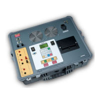
Vanguard Instruments LTCA-40 User Manual (58 pages)
LOAD TAP CHANGER ANALYZER
Brand: Vanguard Instruments
|
Category: Measuring Instruments
|
Size: 1 MB
Table of Contents
Advertisement

Vanguard Instruments LTCA-40 User Manual (58 pages)
LOAD TAP CHANGER ANALYZER
Brand: Vanguard Instruments
|
Category: Measuring Instruments
|
Size: 2 MB
Table of Contents
Advertisement
Related Products
- Vanguard Instruments LTCA-10
- Vanguard Instruments ATO-250
- Vanguard Instruments ATRT-01 S3
- Vanguard Instruments ATRT-01B S3
- Vanguard Instruments ATRT-03
- Vanguard Instruments ATRT-03A
- Vanguard Instruments ATRT-03B
- Vanguard Instruments Auto-Ohm 10
- Vanguard Instruments Auto-Ohm 200 S3
- Vanguard Instruments CT-7000 S3