Table of Contents

Subscribe to Our Youtube Channel
Related Manuals for Vanguard Instruments IRM-5000P


Summary of Contents for Vanguard Instruments IRM-5000P
- Page 1 MODEL IRM-5000P INSTRUCTION MANUAL OPERATING INSTRUCTIONS for the IRM-5000P INSULATION-RESISTANCE METER Vanguard Instruments Company 1710 Grevillea Court Ontario, California 91761 TEL: (909) 923-9390 July 2003 FAX: (909) 923-9391 Rev 1...
- Page 2 MODEL IRM-5000P INSTRUCTION MANUAL SAFETY SUMMARY Only trained operators shall use the IRM-5000P. All devices under test shall be off line and fully isolated. DO NOT SERVICE OR TEST ALONE Do not perform test procedures or service unless another person is also present who is capable of rendering aid and resuscitation.
-
Page 3: Table Of Contents
1.11 Power Source........................7 1.10 Test Terminals ........................8 1.20 Test Probes ........................8 2.0 IRM-5000P SPECIFICATIONS....................9 3.0 IRM-5000P CONTROL PANEL DESCRIPTION..............10 4.0 TEST MODE SUMMARY....................... 11 4.1 Insulation Resistance ( R ) Test..................11 4.2 Polarization Index (PI) Test....................11 4.3 Step Voltage (SV) Test....................... - Page 4 MODEL IRM-5000P USER’S MANUAL Appendix A............................ 38 Appendix B ............................ 39 Appendix C............................ 40...
- Page 5 Table 11.0 Recalling a Test Report ..................... 35 Table 12.0 Printing a Test Report....................35 Table 13.0 Printing a Graphic Report..................36 Table 14.0 Delete a Test Report from Memory................36 Table 15.0 Putting the IRM-5000P under Computer Control............37 Table 16.0 PI Ratio Table ......................38...
- Page 6 Figure 20.0 Resistance vs Time Plot of a DD test..............32 Figure 21.0 Current vs Time Plot of an DD test................32 Figure 22.0 Typical Test Report Directory Printout ..............34 Figure 23.0 Test Terminals of the IRM-5000P ................40...
-
Page 7: Functional Description
The High-Voltage LED will warn the operator of the potential hazard that exists during each discharging period. 1.4 Voltmeter The IRM-5000P will always display on the LCD screen the voltage at the test terminals. Thus, the user can use the IRM-5000P as a voltmeter. Measurable voltage input ranges from 50 to 1250 Volts, ac or dc. -
Page 8: Built-In Thermal Printer
An RS-232C port can be used to interface with an IBM-compatible computer. A Windows™-based Insulation-Resistance Analysis program allows users to retrieve test reports stored in the IRM-5000P. Thus, the user can generate test reports with an office computer. A special feature of the software will also allow the user to overlay several resistance curves on a color monitor. -
Page 9: Test Terminals
1.20 Test Probes Table 3.0 IRM-5000P Cable set ITEM DESCRIPTION Power Cord 5 feet test leads 15 feet test leads RS-232C Cable WARNING Do not touch the test probes of the IRM-5000P during testing. Failure to comply can cause a lethal shock. -
Page 10: Irm-5000P Specifications
MODEL IRM-5000P INSTRUCTION MANUAL 2.0 IRM-5000P SPECIFICATIONS TYPE Insulation Resistance Meter SIZE 19 L by 15 W by 7 H (inches) 48.2 L by 38.2 W by 17.7 (cm) WEIGHT 24 pounds (10.88 Kg) RESISTANCE RANGE +5% 1 M-ohm to 1 T-ohm @ 5 kV... -
Page 11: Irm-5000P Control Panel Description
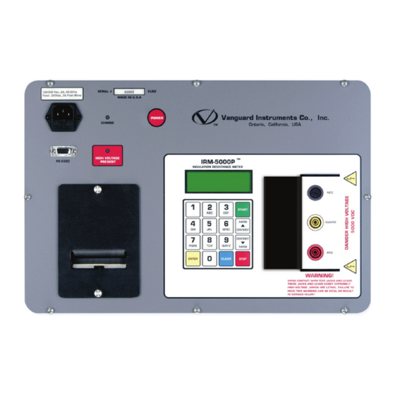
MODEL IRM-5000P USER’S MANUAL 3.0 IRM-5000P CONTROL PANEL DESCRIPTION Figure 1.0 IRM-5000P Controls and Indicators Table 4.0 IRM-5000P Controls and Displays Index no PANEL MARKING FUNCTIONAL DESCRIPTION Power plug and fuse holder 120 Vac, 6A, 50/60Hz Fuse: 250 Vac, 3A Fast-Blow... -
Page 12: Test Mode Summary
(steps) will produce decreasingly lower resistance values. A typical Step Voltage test duration is five minutes. The IRM-5000P will sequentially take resistance readings of the DUT at one-fifth increments of the final test voltage at one minute intervals. Default test voltages are selectable at 2,500 Vdc or 5,000 Vdc. -
Page 13: Operating Procedures
MODEL IRM-5000P INSTRUCTION MANUAL 5.0 OPERATING PROCEDURES 5.1 Insulation Resistance Test Procedure Using Standard Voltages The Insulation Resistance test measures the insulation resistance at selected voltages. Since the insulation resistance is continuously monitored during each test, users can plot resistance values versus time or current versus time. The following table provides the procedure for measuring the insulation resistance. -
Page 14: Insulation Resistance Test In Progress Display
4. The test terminal voltage is always shown at the bottom of the LCD screen. 5. The option of “Print during test,” will command the IRM-5000P to print the resistance readings at 15 seconds, 30 seconds, 45 seconds and every one minute interval. -
Page 15: Insulation Resistance "End Of "Test Displays
MODEL IRM-5000P INSTRUCTION MANUAL 5.3 Insulation Resistance “End of “Test Displays A typical Insulation Resistance result display is shown on Figure 3.0. Res=989.7M 5.05 uA 4998V 0.00uF 10.00 TERMINAL VTG: Figure 3.0 Resistance Result Display The display in Figure 3.0 is interpreted as follows: 1. -
Page 16: Typical Resistance Test Printout
MODEL IRM-5000P INSTRUCTION MANUAL 5.4 Typical Resistance Test Printout A typical Insulation Resistance printout is shown in Figure 6.0. Figure 6.0 Typical Resistance Printout... - Page 17 MODEL IRM-5000P INSTRUCTION MANUAL In Figure 6.0, the Resistance Test printout is interpreted as follows: 1. Time and date of the test are shown on the top of the test report. 2. The test record identification number is shown in the first box of the test report.
-
Page 18: Figure 7.0 Resistance Vs Time Plot
MODEL IRM-5000P USER’S MANUAL 5.5 Typical Resistance Plot and Current Plot A typical resistance versus time and current versus time plots for an Insulation Resistance test are shown in Figures 7.0 and 8.0. Figure 7.0 Resistance vs Time Plot Figure.8.0 Current vs Time Plot... -
Page 19: Polarization Index (Pi) Test Using Standard Voltage
MODEL IRM-5000P INSTRUCTION MANUAL 5.6 Polarization Index (PI) Test Using Standard Voltage The Polarization Index is derived from the ratio of the insulation resistance at ten minutes divided by the insulation value at one minute. Users can use standard voltages of: 500 V, 1000 V, 2500 V, 5000 V, or any selectable voltage from 50V to 5000V. - Page 20 MODEL IRM-5000P USER’S MANUAL Table 6.0 Notes: 1. To select a custom test time, select “2” on step 2. The test duration is selected in minutes. 2. To select a custom test voltage, select “5” on step 3. The test voltage is selectable from 50Vdc to 5000Vdc.
-
Page 21: Pi Test In Progress Display
MODEL IRM-5000P INSTRUCTION MANUAL 5.7 PI Test In Progress Display A typical PI test in progress on the LCD is shown in Figure 9.0. Bat:------- Time: 09:39 Resistance: 1.9305 G Current: 100.7 nA TEST VOLTAGE: 1000V Figure 9.0 Typical PI Test in Progress Display The PI display in Figure 9.0 is interpreted as follows:... -
Page 22: Polarization Index (Pi) Test Print Out
MODEL IRM-5000P USER’S MANUAL 5.9 Polarization Index (PI) Test Print Out A typical Polarization Index Test printout is shown in Figure 11.0. Figure 11.0 Typical Polarization Index (PI) Test Printout... - Page 23 MODEL IRM-5000P INSTRUCTION MANUAL The sample PI printout in Figure 11.0 is interpreted as follows: 1. The time and date of the test are shown at the top of the test report. 2. The test record identification number is shown in the first box of the test report.
-
Page 24: Pi Resistance And Current Plot
MODEL IRM-5000P INSTRUCTION MANUAL 5.10 PI Resistance and Current Plot A typical resistance versus time and current versus time plots for a PI test are shown in Figures 12.0 and 13.0. NOTE The one minute marker is highlighted on both the resistance and the current plots. -
Page 25: Step Voltage (Sv) Test
MODEL IRM-5000P INSTRUCTION MANUAL 5.11 Step Voltage (SV) Test For the Step Voltage test, the IRM-5000P measures the Insulation Resistance at five different voltages. The default test duration for each test voltage is one minute or a total test time of five minutes. A non-standard test time can be selected by the user. Using the standard 2,500V test voltage, the IRM-5000P will step through 500V, 1,000V, 1,500V, 2,000V, and 2,500V. -
Page 26: Step Voltage Test In Progress Display
MODEL IRM-5000P INSTRUCTION MANUAL STEP DESCRIPTION ACTION RESULTING DISPLAY View Test Results Select “ENTER” key 99.04M @ 03:00, 1502V 2499V 0.00F 05:00 @ 3 minutes View Test Results Select “ENTER” key 99.02M @ 04:00, 2009V 2499V 0.00F 05:00 @ 4 minutes View Test Results Select “ENTER”... -
Page 27: Step Voltage Test Result Display (Screen #1)
MODEL IRM-5000P INSTRUCTION MANUAL 5.13 Step Voltage Test Result Display (Screen #1) A typical Step Voltage Test result is shown on Figure 15.0. 98.09M @ 01:00, 501V 2499V 0.00F 5:00 Figure 15.0 Step Voltage Test Result Display @ 1 Minute The display in Figure 15.0 is interpreted as follows:... -
Page 28: Step Voltage Test Print Out
MODEL IRM-5000P INSTRUCTION MANUAL 5.14 Step Voltage Test Print Out A typical Step Voltage Test printout is shown in Figure 16.0. Figure 16.0 Typical Step-Voltage Test Printout... -
Page 29: Step Voltage Test Resistance And Current Plots
MODEL IRM-5000P INSTRUCTION MANUAL The readout in Figure 16.0 is interpreted as follows: 1. The time and date of the test are shown at the top of the test report. 2. The test record identification number is shown in the first box of the test report. -
Page 30: Dielectric Discharge (Dd) Test
5.16 Dielectric Discharge (DD) Test The Dielectric Discharge test measures the dielectric absorption of a tested material. A typical DD test is timed for 30 minutes. The IRM-5000P performs the DD test automatically. Follow the steps below to start a DD test. -
Page 31: Dielectric Discharge Test Result Display
MODEL IRM-5000P INSTRUCTION MANUAL Table 8.0 Notes: 1. To select a custom test time, select “2” in step 3. Test duration is selected in minutes. 2. To select a custom test voltage, select “2” in step 4. Test voltages are selectable from 50 V dc to 500 V dc. -
Page 32: Dielectric Discharge Test Printout
MODEL IRM-5000P INSTRUCTION MANUAL 5.18 Dielectric Discharge Test Printout A typical Dielectric Discharge Test printout is shown in Figure 19.0. Figure 19.0 Typical Dielectric Discharge Test Printout The display in Figure 19.0 is interpreted as follows: 1. The time and date of the test are shown at the top of the test report. -
Page 33: Dielectric Discharge Voltage Vs Time And Current Vs Time Plots
MODEL IRM-5000P INSTRUCTION MANUAL 5.19 Dielectric Discharge Voltage vs Time and Current vs Time Plots The resistance and current plots for the DD test are shown in Figures 20.0 and 21.0. Figure 20.0 Resistance vs Time Plot of a DD test... -
Page 34: Save Test Report In Memory
MODEL IRM-5000P INSTRUCTION MANUAL 5.20 Save Test Report In Memory The IRM-5000P is capable of saving up to 90 test reports in the Flash EEPROM. The feature allows the user to recall test reports generated in the field, which can then be printed in an office or down-loaded to a computer. -
Page 35: Figure 22.0 Typical Test Report Directory Printout
MODEL IRM-5000P INSTRUCTION MANUAL Figure 22.0 Typical Test Report Directory Printout... -
Page 36: Recall Test Report From Memory
MODEL IRM-5000P INSTRUCTION MANUAL 5.22 Recall Test Report From Memory To recall a specific test report from the memory, follow the steps below in Table 11.0. The test report can then be printed. Table 11.0 Recalling a Test Report STEP... -
Page 37: Print Graphic Test Report
MODEL IRM-5000P INSTRUCTION MANUAL 5.24 Print Graphic Test Report Follow the steps in Table 13.0 below to print a graphic report. Table 13.0 Printing a Graphic Report STEP DESCRIPTION ACTION RESULTING DISPLAY Select Utilities menu Select key “2” 1. PRINT 2. SAVE/RES 3. -
Page 38: Computer Interface
3.SETUP Select Set Up menu Select key “3” 1.TEST ID 2.CLOCK 3.COMP INT 4.50/60Hz Select Computer ITF Select key “3” COMPUTER INTERFACE MODE NOTE To return the IRM-5000P to the stand-alone mode, press the STOP key on the front panel. -
Page 39: Table 16.0 Pi Ratio Table
MODEL IRM-5000P INSTRUCTION MANUAL Appendix A Polarization Index Ratio The Polarization Index (PI) number is derived from the ratio of the resistance value at ten minutes to the resistance value reading at one minute. Since the resistance readings are taken very closely in time, the temperature is virtually the same at both resistance measurement times. - Page 40 The Dielectric Discharge test incorporated in the IRM-5000P has a standard test voltage of 500V and a standard test time of 30 minutes. During the testing time some charge migrates into the dielectric material under test, as described above.
-
Page 41: Figure 23.0 Test Terminals Of The Irm-5000P
Positive HV Test lead to the Guard lead. These currents are not measured by the IRM-5000P. The cable itself will also have some inherent leakage current that will flow from the Positive HV lead, through the cable, and out the Negative HV lead. - Page 42 MODEL IRM-5000P INSTRUCTION MANUAL www.vanguard-instruments.com...
Need help?
Do you have a question about the IRM-5000P and is the answer not in the manual?
Questions and answers