
Subscribe to Our Youtube Channel
Related Manuals for Vanguard Instruments TRM-20


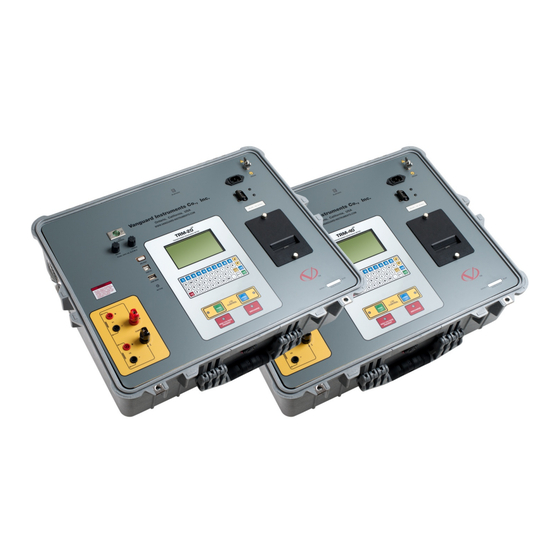
Summary of Contents for Vanguard Instruments TRM-20
- Page 1 TRM-20 and TRM-40 TRANSFORMER RESISTANCE METERS USER’S MANUAL Vanguard Instruments Company, Inc. 1520 S. Hellman Ave. Ontario, California 91761, USA TEL: (909) 923-9390 August 2017 FAX: (909) 923-9391 Revision 1.5...
-
Page 2: Safety Summary
SAFETY WARNING AND CAUTIONS The TRM-20/40 shall be used only by trained operators. All transformers under test shall be off-line and fully isolated. DO NOT MODIFY TEST EQUIPMENT To avoid the risk of introducing additional or unknown hazards, do not install substitute parts or perform any unauthorized modification to any TRM-20/40 test unit. -
Page 3: Table Of Contents
REV 1.5 TRM-20 AND TRM-40 USER’S MANUAL TABLE OF CONTENTS CONVENTIONS USED IN THIS DOCUMENT ............... 1 INTRODUCTION ........................2 General Description and Features ................... 2 Technical Specifications ....................4 TRM Controls and Indicators ................... 5 PRE-TEST SETUP ........................6 Operating Voltages ...................... - Page 4 TRM-20 AND TRM-40 USER’S MANUAL REV 1.5 LIST OF FIGURES Figure 1. TRM-20/40 Controls and Indicators ................5 Figure 2. Typical Connections to a Load Tap Changer (LTC) ............17 Figure 3. Typical TRM Connections Diagram for A Dynamic Resistance Test ......17 Figure 4.
-
Page 5: Conventions Used In This Document
REV 1.5 TRM-20 A ND TRM-40 USER’S MA ANUAL CONVE ENTIONS S USED IN N THIS DO OCUMEN This docu ument uses the followin ng conventio ons: • Both the TRM-20 0 and TRM-4 40 are simply y referred to o as “TRM”... -
Page 6: Introduction
(primary and secondary windings of a transformer). Both the TRM-20 and TRM-40 can provide a fast and stable reading of very large transformers by utilizing a 60Vdc power supply. The TRM-20 is capable of outputting a selectable test current from 1A to 20A while the TRM-40’s test current is selectable from 1A to 40A. - Page 7 REV 1.5 TRM-20 AND TRM-40 USER’S MANUAL User Interface The TRM features a back-lit graphic LCD screen (124x64) that is clearly viewable in both bright sunlight and low-light levels. An alpha-numeric keypad is used to enter test information and to operate the unit.
-
Page 8: Technical Specifications
TRM-20 A AND TRM-40 0 USER’S MA ANUAL RE V 1.5 Technical S Specificatio Table 1. TRM-20/4 0 Technical Specification TYPE Portable tran sformer windin ng resistance m meter HYSICAL SPEC CIFICATIONS 21” W x 17” H H x 9” D (53 cm m x 43 cm x 24 cm);... -
Page 9: Trm Controls And Indicators
REV 1.5 TRM-20 AND TRM-40 USER’S MANUAL TRM Controls and Indicators The TRM-20/40’s controls and indicators are shown in Figure 1. The purpose of the controls and indicators may seem obvious, but users should become familiar with them before using the TRM. -
Page 10: Pre-Test Setup
The TRM’s built-in thermal printer uses 2.5-inch wide thermal paper for printing test results. To maintain the highest print quality and to avoid paper jams, the use of thermal paper supplied by Vanguard Instruments Company is highly recommended. Additional paper can be ordered from the following sources: Vanguard Instruments Co, Inc. -
Page 11: Replacing The Thermal Printer Paper
REV 1.5 TRM-20 A ND TRM-40 USER’S MA ANUAL Replacing t the Therma al Printer P Paper The roll o of thermal p aper is hous sed inside a dispenser un nderneath t he printer co over. To rep lace... -
Page 12: Operating Procedures
TRM-20 AND TRM-40 USER’S MANUAL REV 1.5 OPERATING PROCEDURES Configuring the LTCA Software for use with the TRM The TRM can be used with a PC using the Vanguard LTCA software. Follow the steps below to properly connect the TRM and configure the LTCA application to recognize the unit. - Page 13 REV 1.5 TRM-20 AND TRM-40 USER’S MANUAL f. Launch the LTCA application and then click on the “Settings” icon. The following window will be displayed: Make sure the “Use USB Port” option is UN-checked. Then, from the “COM Port” drop- down menu, select the COM port that corresponds to the port that the TRM is connected to.
-
Page 14: Connecting The Trm To A Pc Via Bluetooth
TRM-20 AND TRM-40 USER’S MANUAL REV 1.5 Connecting the TRM to a PC via Bluetooth The TRM can also be connected wirelessly to a PC using Bluetooth. To connect the unit via Bluetooth, it must first be paired with the PC. Follow the steps below to pair the TRM to a PC... - Page 15 REV 1.5 TRM-20 AND TRM-40 USER’S MANUAL The TRM will be listed as “TRM S/N” where S/N is the device’s serial number. Click on the icon for the TRM and then click on the “Next” button. d. The following window will be displayed asking for a secret key to connect to the TRM: Type the word “default”...
- Page 16 The following confirmation screen will be displayed: Click on the “Finish” button. g. The TRM-20 will now be displayed in the “My Bluetooth Places” window: Note the port number listed under the device name. In the above case, the port number...
- Page 17 REV 1.5 TRM-20 AND TRM-40 USER’S MANUAL For Windows 7: a. Make sure the TRM is turned on. Then double click on the Bluetooth system tray icon (on the bottom right corner of your computer screen): b. The “Bluetooth Devices” window will be displayed:...
- Page 18 TRM-20 AND TRM-40 USER’S MANUAL REV 1.5 c. All nearby Bluetooth devices will be listed: The TRM will be listed as “TRM S/N” where S/N is the device’s serial number. Click on the icon for the TRM and then click on the “Next” button.
- Page 19 REV 1.5 TRM-20 AND TRM-40 USER’S MANUAL e. The following window will be displayed: Type the word “default” (without the quotes and in all lower-case) in the text box and click on the “Next” button. f. The following screen will be displayed:...
- Page 20 TRM-20 AND TRM-40 USER’S MANUAL REV 1.5 g. The TRM will now be listed under “Bluetooth Devices”: Right click on the TRM-20 icon and select “Properties” from the pop-up menu. h. The properties window will be displayed. Click on the “Hardware” tab: Note the port number listed after the device name (COM23 in the above example).
-
Page 21: Typical Connections To A Load Tap Changer (Ltc)
REV 1.5 TRM-20 A ND TRM-40 USER’S MA ANUAL Typical Con nnections to a Load T Tap Chang ger (LTC) igure 2. Typi ical Connect tions to a Loa ad Tap Chan nger (LTC) Typical TRM M-20/40 Ca able Conne ections •... -
Page 22: Figure 4. Typical Single Phase Trm Connections
TRM-20 AND TRM-40 USER’S MANUAL REV 1.5 Figure 4. Typical Single Phase TRM Connections Figure 5. Typical TRM Connections Diagram for 2 Windings... -
Page 23: General Procedures
REV 1.5 TRM-20 A ND TRM-40 USER’S MA ANUAL General Pro ocedures The main n steps for u sing the TRM M are outline ed below: a. G Ground the T TRM to the s ubstation gr round. Always conn... -
Page 24: Entering Test Record Header Information
TRM-20 AND TRM-40 USER’S MANUAL REV 1.5 Entering Test Record Header Information You can enter the test record header information before performing tests. The record header includes identifying information such as the company, station, circuit, model number, etc. Once the header information has been entered, it will apply to all subsequent test records. To enter the header information: a. - Page 25 REV 1.5 TRM-20 AND TRM-40 USER’S MANUAL d. The following screen will be displayed: STATION: ↑ ↓ TO POSITION "ENTER" TO ACCEPT [ENTER] Type the station name using the keypad and then press the key. e. The following screen will be displayed: CIRCUIT: ↑...
- Page 26 TRM-20 AND TRM-40 USER’S MANUAL REV 1.5 h. The following screen will be displayed: SERIAL NUMBER: ↑ ↓ TO POSITION "ENTER" TO ACCEPT [ENTER] Type the serial number using the keypad and then press the key. i. The following screen will be displayed: KVA RATING: ↑...
-
Page 27: Setting The Date And Time
REV 1.5 TRM-20 AND TRM-40 USER’S MANUAL Setting the Date and Time To set the date and time: a. Start from the “START-UP” menu: 11/01/11 1. RUN TEST 09:06:21 2. SETUP 22°C 72°F 3. USER DIAGNOSTICS Press the key (SETUP) b. -
Page 28: Setting The Interface Language
TRM-20 AND TRM-40 USER’S MANUAL REV 1.5 Setting the Interface Language Follow the steps below to set the interface language (English, Spanish, or Turkish): a. Start from the “START-UP” menu: 11/01/11 1. RUN TEST 09:06:21 2. SETUP 22°C 72°F 3. USER DIAGNOSTICS Press the key (SETUP). -
Page 29: Performing A Resistance Test
REV 1.5 TRM-20 AND TRM-40 USER’S MANUAL Performing a Resistance Test a. Start from the “START-UP” menu: 11/01/11 1. RUN TEST 09:06:21 2. SETUP 22°C 72°F 3. USER DIAGNOSTICS Press the key (RUN TEST). b. The following screen will be displayed: 1. - Page 30 TRM-20 AND TRM-40 USER’S MANUAL REV 1.5 e. The following menu will be displayed: SELECT TEST CURRENT: 1. 1A 2. 5A 3. 10A 4. 20A 5. 40A 6. CUSTOM Select the test current by pressing the corresponding numeric key on the keypad. Press key (CUSTOM) if you would like to enter a custom test current and then enter the current (between 1A-40A) on the next screen.
- Page 31 REV 1.5 TRM-20 AND TRM-40 USER’S MANUAL ° 230.0 ↑↓ to adjust tk "ENTER" to accept [PAPER ∧ You can increase the Tk value by 0.5°C increments by pressing the Contrast] key. [PAPER ∨ You can decrease the Tk value by 0.5°C increments by pressing the Contrast] key.
- Page 32 TRM-20 A AND TRM-40 0 USER’S MA ANUAL RE V 1.5 NTER] ress the key t to confirm t he reference e temperatu ure setting. e TRM will c calculate the e equivalent resistance v value at this mperature. NOTE i.
- Page 33 REV 1.5 TRM-20 A ND TRM-40 USER’S MA ANUAL After the TRM M finishes its s internal ca libration, th e following s screen will b be displayed *XFM MR CHARG ING* ease wai t... ** XFMR R ENERGI ZED! **...
- Page 34 TRM-20 AND TRM-40 USER’S MANUAL REV 1.5 Once the data is saved, the following screen will be displayed: TEST IN PROGRESS > < TEST SAVED! 10.01 AMPS mΩ 1.465 mΩ 1.448 ** XFMR ENERGIZED! ** [STOP] Press the key to stop running the test. The test results will be displayed as...
- Page 35 REV 1.5 TRM-20 AND TRM-40 USER’S MANUAL n. The following screen will be displayed: KEEP THIS READING? 1. YES 2. NO 1. YES Press the key (YES) to save the reading. One of the following screens will be displayed: The following screen will be displayed if there is no previous data in the memory: >...
- Page 36 TRM-20 AND TRM-40 USER’S MANUAL REV 1.5 2. NO If you do not wish to save the reading, press the key (NO) and continue to step o. o. The following screen will be displayed: RUN ANOTHER TEST? 1. YES 2. NO Press the key (YES) to run another test.
-
Page 37: Figure 6. Typical Resistance Test Results Printout
REV 1.5 TRM-20 A ND TRM-40 USER’S MA ANUAL q. T he following g screen will be displaye record n number 0 has been n saved! e record num mber is auto matically ass signed and i ncremented d by the TRM M . -
Page 38: Performing A Load Tap Changer / Voltage Regulator Resistance Test
TRM-20 AND TRM-40 USER’S MANUAL REV 1.5 3.10 Performing a Load Tap Changer / Voltage Regulator Resistance Test The Load Tap Changer/Voltage Regulator Resistance Test can be used to conveniently measure the resistance at each tap position. Once the number of taps has been entered, the TRM will request the user to set the tap position, starting with the lower taps, then to neutral, and then to the raise taps. - Page 39 REV 1.5 TRM-20 AND TRM-40 USER’S MANUAL d. The following screen will be displayed ENTER NUMBER OF RAISE TAPS, NOT COUNTING NEUTRAL (1-23): Type the number of taps the LTC or Voltage Regulator has using the alpha-numeric [ENTER] keypad, and then press the key.
- Page 40 TRM-20 AND TRM-40 USER’S MANUAL REV 1.5 g. The following screen will be displayed: SELECT TEST CURRENT: 1. 1A 2. 5A 3. 10A 4. 20A 5. 40A 6. CUSTOM Select the test current by pressing the corresponding numeric key on the keypad. Press key (CUSTOM) if you would like to enter a custom test current and then enter the current (between 1A-40A) on the next screen.
- Page 41 REV 1.5 TRM-20 AND TRM-40 USER’S MANUAL ° 230.0 ↑↓ to adjust tk "ENTER" to accept [PAPER ∧ You can increase the Tk value by 0.5°C increments by pressing the Contrast] key. [PAPER ∨ You can decrease the Tk value by 0.5°C increments by pressing the Contrast] key.
- Page 42 TRM-20 A AND TRM-40 0 USER’S MA ANUAL RE V 1.5 NTER] ress the key t to confirm t he reference e temperatu ure setting. e TRM will c calculate the e equivalent resistance v value at this mperature. NOTE k.
- Page 43 REV 1.5 TRM-20 AND TRM-40 USER’S MANUAL After the TRM finishes its internal calibration, the following screen will be displayed: *XFMR CHARGING* please wait... 1.01 AMPS ** XFMR ENERGIZED! ** n. The TRM determines when the resistance reading is stable and displays the resistance...
- Page 44 TRM-20 AND TRM-40 USER’S MANUAL REV 1.5 p. After saving the readings, the following screen will be displayed: set tap to 2 lower ("START" to CONTINUE) ** XFMR ENERGIZED! ** Set the LTC or Voltage Regulator tap position to the position indicated on the LCD screen...
- Page 45 REV 1.5 TRM-20 AND TRM-40 USER’S MANUAL record number 02 has been saved! Press any key to return to the “START-UP” menu. 2. NO If you do not wish to save the test record, press the key (NO). The following...
-
Page 46: Figure 7. Typical Ltc/Voltage Regulator Test Report Printout
TRM-20 AND TRM-40 USER’S MANUAL REV 1.5 Figure 7. Typical LTC/Voltage Regulator Test Report Printout... -
Page 47: Performing A Special Resistance Test
REV 1.5 TRM-20 AND TRM-40 USER’S MANUAL 3.11 Performing a Special Resistance Test The Special Resistance Test is used to conduct a resistance test for a pre-defined period ranging from 1 to 45 minutes. The resistance data is recorded at one minute intervals. Use the steps below to perform a Special Resistance Test: a. - Page 48 TRM-20 AND TRM-40 USER’S MANUAL REV 1.5 d. The following screen will be displayed: enter special test time minutes (1-45) Enter the test time (between 1 to 45 minutes) using the alpha-numeric keypad, and [ENTER] then press the key. e. The following screen will be displayed: SELECT TEST CURRENT: 1.
- Page 49 REV 1.5 TRM-20 AND TRM-40 USER’S MANUAL Press the key (COPPER, Tk=234.5) to select copper as the winding material. Continue to step g. Press the key (ALUMINUM, Tk=225) to select aluminum as the winding material. Continue to step g. Press the key (MANUALLY ENTER Tk) to manually enter the Tk value.
- Page 50 TRM-20 AND TRM-40 USER’S MANUAL REV 1.5 h. The following screen will be displayed: REFERENCE TEMP: ° ° 75.0 167.0 ↑↓ to adjust tk "ENTER" to accept [PAPER ∧ Contrast] [PAPER ∨ Contrast] Use the keys to adjust the reference temperature.
- Page 51 REV 1.5 TRM-20 AND TRM-40 USER’S MANUAL k. The following screen will be displayed momentarily: calibrating please wait... After the TRM finishes its internal calibration, the following screen will be displayed: *XFMR CHARGING* please wait... 1.01 AMPS ** XFMR ENERGIZED! ** This is only an informational screen to remind the operator that a test is in progress.
- Page 52 TRM-20 A AND TRM-40 0 USER’S MA ANUAL RE V 1.5 m. T he following g screen will be displaye SAVE TH IS RECOR 1. YES 2. NO 1. YES Press (YES) to sav e the test re ecord. Contin nue to step 2.
-
Page 53: Figure 8. Typical Special Test Report Printout
REV 1.5 TRM-20 AND TRM-40 USER’S MANUAL Figure 8. Typical Special Test Report Printout... -
Page 54: Performing A Dynamic Ltc Test
TRM-20 A AND TRM-40 0 USER’S MA ANUAL RE V 1.5 3.12 Performing a Dynami c LTC Tes The Dyna amic LTC Tes st is used to conduct a re esistance te st while the LTC or Volta age Regulato... - Page 55 REV 1.5 TRM-20 AND TRM-40 USER’S MANUAL d. The following screen will be displayed: SET LTC/VREG To LOWEST TAP POSITION. PRESS ANY KEY WHEN READY Set the LTC or Voltage Regulator to the lowest position either manually or by pressing...
- Page 56 TRM-20 AND TRM-40 USER’S MANUAL REV 1.5 READY TO CAPTURE DATA PRESS "ENTER" - OR - LTC RAISE/LOWER TO START TIMING... [ENTER] [RAISE] [LOWER] Press the key or the LTC key to continue. g. The TRM will start capturing data and the following screen will be displayed:...
- Page 57 REV 1.5 TRM-20 AND TRM-40 USER’S MANUAL 1. YES Press the key (YES) to save the test results to the connected USB Flash drive. The following screen will be displayed: REC_001 SAVED TO THUMB DRIVE. Press any key to return to the “START-UP” menu.
-
Page 58: Figure 9. Typical Dynamic Ltc Test Results Printout Showing An Opened Circuit
TRM-20 AND TRM-40 USER’S MANUAL REV 1.5 Figure 9. Typical Dynamic LTC Test Results Printout Showing an Opened Circuit... -
Page 59: Performing A Diagnostic Test
REV 1.5 TRM-20 AND TRM-40 USER’S MANUAL 3.13 Performing a Diagnostic Test In diagnostic mode, the TRM can run a resistance test, display the sense voltages, and test current on the TRM. This feature can be used to verify the TRM’s voltage and current readings against an external meter. - Page 60 TRM-20 AND TRM-40 USER’S MANUAL REV 1.5 d. The following screen will be displayed: - USER DIAG TEST - "START" TO RUN TEST "STOP" TO ABORT [START] Press the key. e. The V1, V2, and test current (I) will be displayed as shown below: USER DIAGNOSTICS V1 = 35.86...
-
Page 61: Demagnetizing The Transformer Core
REV 1.5 TRM-20 AND TRM-40 USER’S MANUAL 3.14 Demagnetizing the Transformer Core You can demagnetize the transformer core using the steps below: a. Start from the “Start-Up” menu: 11/07/11 1. RUN TEST 08:49:15 2. SETUP 22°C 72°F 3. USER DIAGNOSTICS... - Page 62 TRM-20 AND TRM-40 USER’S MANUAL REV 1.5 e. The degaussing process will start and updates will be displayed on the screen as shown below: * DEGAUSSING XFMR * -> SETTING CORE... ** XFMR ENERGIZED! ** * DEGAUSSING XFMR * SETTING CORE...
-
Page 63: Working With Test Records
REV 1.5 TRM-20 AND TRM-40 USER’S MANUAL 3.15 Working with Test Records 3.15.1. Viewing the Contents of the Working Memory Whenever a test is performed and the reading is kept, the data is temporarily stored in the TRM’s working memory. You can view the test reading in the unit’s working memory using the steps below: a. - Page 64 TRM-20 AND TRM-40 USER’S MANUAL REV 1.5 2. PRINT TO PRINTER Press the key (PRINT TO PRINTER) to print the test record on the unit’s thermal printer. You will then be returned to the “START-UP” menu.
-
Page 65: Saving Test Results To A Test Record
REV 1.5 TRM-20 A ND TRM-40 USER’S MA ANUAL 3.15.2. S Saving Tes st Results to a Test R Record After per rforming a te est, the user r is presente ed the option n to save the e test results s to the unit’... - Page 66 TRM-20 AND TRM-40 USER’S MANUAL REV 1.5 If a USB Flash drive is connected to the unit, continue to step d. If a USB Flash drive is NOT connected to the unit, continue to step e. d. The following screen will be displayed: 1.
-
Page 67: Restoring A Test Record From Flash Eeprom
REV 1.5 TRM-20 A ND TRM-40 USER’S MA ANUAL 3.15.3. R Restoring a Test Rec cord From Flash EEP PROM Use the s steps below to restore a a test record from the TR RM’s interna al Flash EEPR ROM to the... - Page 68 TRM-20 A AND TRM-40 0 USER’S MA ANUAL RE V 1.5 d. The following g screen will be displaye REST TORE RECO 1. ENTER R RECORD NUMBER 2. SCROL LL TO SEL LECT If y you have a U USB Flash driv ve inserted in the unit’s...
- Page 69 REV 1.5 TRM-20 AND TRM-40 USER’S MANUAL RECORD RESTORED! PRINT RECORD? 1.YES 2.NO Press the key (YES) if you would like to print the restored test record on the unit’s built-in thermal printer. You will be returned to the “START-UP” menu after printing is finished.
- Page 70 TRM-20 AND TRM-40 USER’S MANUAL REV 1.5 RECORD RESTORED! PRINT RECORD? 1.YES 2.NO Press the key (YES) if you would like to print the restored test record on the unit’s built-in thermal printer. You will be returned to the “START-UP” menu after printing is finished.
-
Page 71: Restoring A Test Record From A Usb Flash Drive
REV 1.5 TRM-20 AND TRM-40 USER’S MANUAL 3.15.4. Restoring a Test Record From a USB Flash Drive Use the steps below to restore a test record from a USB Flash drive to the TRM’s working memory: a. Make sure the USB Flash drive containing the test record(s) is inserted in the TRM’s USB Flash drive port (“USB MEM”... - Page 72 TRM-20 AND TRM-40 USER’S MANUAL REV 1.5 d. The following screen will be displayed: 1. INTERNAL STORAGE 2. THUMB DRIVE Press the key (THUMB DRIVE). e. The following screen will be displayed: RESTORE THUMB DRIVE REC_ Type the record number that you would like to restore using the alpha-numeric keypad...
-
Page 73: Copying Test Records To A Usb Flash Drive
REV 1.5 TRM-20 AND TRM-40 USER’S MANUAL 3.15.5. Copying Test Records to a USB Flash Drive Use the steps below to copy one or all test records from the unit’s Flash EEPROM to a connected USB Flash drive: a. Make sure a USB Flash drive is connected to the unit’s “USB MEM” port, and then start from the “START-UP”... - Page 74 TRM-20 AND TRM-40 USER’S MANUAL REV 1.5 d. The following screen will be displayed: COPY REC TO THUMB DRV 1.COPY SINGLE RECORD 2.COPY ALL RECORDS 1. COPY SINGLE RECORD Press the key (COPY SINGLE RECORD) to copy a single test record from the unit’s Flash EEPROM to the connected USB Flash drive.
- Page 75 REV 1.5 TRM-20 AND TRM-40 USER’S MANUAL 2. COPY ALL RECORDS Press the key (COPY ALL RECORDS) to copy all test records from the TRM’s Flash EEPROM to the connected USB Flash drive. All test records will be copied from the unit to the connected USB Flash drive. The following screen will be...
-
Page 76: Printing A Test Record Directory
TRM-20 AND TRM-40 USER’S MANUAL REV 1.5 3.15.6. Printing a Test Record Directory Use the steps below to print a directory of the test records stored in the TRM’s Flash EEPROM: a. Start from the “START-UP” menu: 11/10/11 1. RUN TEST 12:13:15 2. -
Page 77: Figure 10. Typical Test Record Directory Printout
REV 1.5 TRM-20 AND TRM-40 USER’S MANUAL d. The following screen will be displayed: PRINT DIRECTORY 1. FULL DIRECTORY 2. SHORT DIRECTORY Press the key (FULL DIRECTORY) to print the entire directory of test records. After the directory is printed, you will be returned to the “START-UP” menu. -
Page 78: Erasing Test Records From The Flash Eeprom
TRM-20 AND TRM-40 USER’S MANUAL REV 1.5 3.15.7. Erasing Test Records from the Flash EEPROM Follow the steps below to erase test records from the unit’s Flash EEPROM: a. Start from the “START-UP” menu: 11/10/11 1. RUN TEST 12:13:15 2. SETUP 22°C... - Page 79 REV 1.5 TRM-20 A ND TRM-40 USER’S MA ANUAL d. T he following g screen will be displaye ASE RECO 1. ERASE E SINGLE E REC. 2. ERASE E ALL RE ECORDS "ST OP" TO E EXIT If y you have a U...
- Page 80 TRM-20 AND TRM-40 USER’S MANUAL REV 1.5 RECORD NUMBER 21 ERASED! Press any key to return to the “START-UP” menu. 2. ERASE ALL RECORDS Press the key (ERASE ALL RECORDS) to erase all records stored in the TRM’s Flash EEPROM. The following screen will be displayed:...
-
Page 81: Erasing Test Records From A Usb Flash Drive
REV 1.5 TRM-20 AND TRM-40 USER’S MANUAL 3.16 Erasing Test Records from a USB Flash Drive Follow the steps below to erase test records from a USB Flash drive: a. Make sure a USB Flash drive is connected to the unit’s “USB MEM” port, and then start from the “START-UP”... - Page 82 TRM-20 AND TRM-40 USER’S MANUAL REV 1.5 e. The following screen will be displayed: ERASE RECORD 1. ERASE SINGLE REC. 2. ERASE ALL RECORDS "STOP" TO EXIT 1. ERASE SINGLE REC. Press the key (ERASE SINGLE REC.) to erase a single test record from the connected USB Flash drive.
- Page 83 REV 1.5 TRM-20 AND TRM-40 USER’S MANUAL [STOP] Press the key if you do not want to erase all the test records. You will be returned to the “START-UP” menu. [ENTER] Press the key to proceed with deleting all the test records from the connected USB Flash drive.
-
Page 84: Converting Resistance Measurements
TRM-20 AND TRM-40 USER’S MANUAL REV 1.5 3.17 Converting Resistance Measurements The TRM can convert the resistance reading of the device under test at its present temperature to the equivalent resistance value at a different temperature. The conversion is accomplished... - Page 85 1520 S. Hellman Ave • Ontario, CA 91761 • USA Phone: 909-923-9390 • Fax: 909-923-9391 www.vanguard-instruments.com Copyright © 2017 by Vanguard Instruments Company, Inc. TRM-20/40 User’s Manual • Revision 1.5 • August 1, 2017 • TA...
Need help?
Do you have a question about the TRM-20 and is the answer not in the manual?
Questions and answers