Table of Contents

Related Manuals for Vanguard Instruments CT-7500


Summary of Contents for Vanguard Instruments CT-7500
- Page 1 OPERATING INSTRUCTIONS For the Model CT-7500 A Digital Circuit-Breaker Analyzer Manufactured by Vanguard Instruments Co., Inc. 1711 Grevillea Ct. Ontario, California 91761 TEL: (909) 923-9390 Jan 2001 FAX: (909) 923-9391 Rev 2...
-
Page 2: Table Of Contents
7.1 CT-7500 Operating Voltage ....................10 7.2 CT-7500 Main Power Fuse ....................10 7.3 CT-7500 Printer and Printer Paper ..................10 7.4 CT-7500 Printer Paper Control .. - Page 3 A. ITE Circuit Breaker Model 14.4K Timing Chart ................I B. CT-7500 Test Plan for ITE Circuit Breaker Model 14.4K................II C. CT-7500 Timing Chart for ITE Circuit Breaker Model 14.4K............III D.
- Page 4 OPERATING INSTRUCTIONS LIST OF FIGURES Figure 5-1. CT-7500 Control Panel ......................6 Figure 8-1. Typical Circuit-Breaker Test Cable Hookup ................14 Figure 8-2. Typical Series Contacts Test Cable hookup ................14 Figure 8-3.
- Page 5 MODEL CT-7500 OPERATING INSTRUCTIONS...
-
Page 7: Introduction
(A/D) to determine the state of the contact (close, or open, or insertion resistor). The CT-7500 records the A/D reading at a 10 KHz rate, and stores these readings in memory. The contact/resistor time is then derived from data stored in memory. -
Page 8: Contact Timing Channels
“ARM” switch during a test to complete the initiate circuit. The CT-7500 can also store up to 200 breaker-timing test records and 45 breaker test-plans in FLASH EEPROM. Stored timing test records can be recalled and printed or transferred to the PC. -
Page 9: Built-In Thermal Printer
An Ink-Jet printer is supplied with each CT-7500. 2.2.9 Computer Interface Capabilities A built-in RS-232C port lets timing shots stored in CT-7500 EEPROMs to be down-loaded to an IBM-compatible PC. Windows-based (Windows 95, Windows 98, Windows Me, Windows 2000, and Windows NT) Breaker Analysis Software is supplied with the CT-7500. This software allows the user to: Time Circuit breakers from a PC. -
Page 10: Ct-7500 Display Control Switches
Contact bounce time (Time-Travel Test). Contact spread time (Time-Travel Test). NOTE The CT-7500 can detect insertion resistors in a 10-7000 ohm range. Resistances over 7000 ohms are detected as an open contact. 3.2 Mechanical Measurement Results Each digital transducer channel provides the following test results: Breaker stroke (Time-Travel Test). -
Page 11: Digital Voltage Input Results
NOTE 1. If the CT-7500 initiates the OPEN test or CLOSE test under the Quick-Shot test, the test report will show OPEN or CLOSE coil current reading and current wave form. -
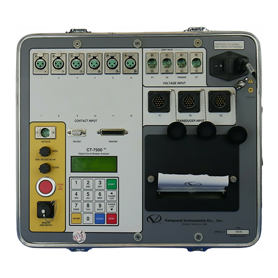
Page 12: Figure 5-1. Ct-7500 Control Panel
MODEL CT-7500 OPERATING INSTRUCTIONS Figure 5-1. CT-7500 Control Panel Rev 2 Jan 2001... -
Page 13: Table 5-1 Model Ct-7500 Controls And Display
MODEL CT-7500 OPERATING INSTRUCTIONS Table 5-1. Model CT-7500 Controls and Displays Fig. 5-1 Index no. PANEL MARKING FUNCTIONAL DESCRIPTION CONTACT INPUT (1-12) Connector, 3-pin: each input is a continuity (dry) sensor for detecting a contact closing or opening (a timing input to the processor). - Page 14 MODEL CT-7500 OPERATING INSTRUCTIONS Table 5-1. Model CT-7500 Controls and Displays (cont’) Fig. 5-1 Index no. PANEL MARKING FUNCTIONAL DESCRIPTION INITIATE Connector, 4-pin; switching circuit for operating the circuit breaker being tested. RS-232C Connector, 9-pin:RS-232C computer interface. Rev 2 Jan 2001...
-
Page 15: Ct-7500 Analyzer Specifications
Back-lighted LCD screen: 4 lines by 20 characters, sunlight viewable HARD-COPY PRINTOUT Contact travel waveforms & tabulated results print on 4.5-inch thermal paper Built-in parallel printer port. CT-7500 produces both graphic and tabulated test COLOR PRINTER results in color on 8.5 by 11 (inches) paper via external ink-jet printer... - Page 16 MODEL CT-7500 OPERATING INSTRUCTIONS One year warranty on parts and labor; post-warranty service contracts available WARRANTY Rev 2 Jan 2001...
-
Page 17: Ct-7500 Special Features
7.0 CT-7500 Special Features 7.1 CT-7500 Operating Voltages The CT-7500 operating voltage is selectable between 110/120 V, 50/60 Hz or 220/240 V, 50/60 Hz. Voltage selection is set by one jumper/connector on the Initiate PCB (JP3) and one jumper/connector on the Power Supply PCB (JP1). Jumper setting for both connectors is shown in table 7-1. -
Page 18: Replacing Ct-7500 Thermal Paper
MODEL CT-7500 OPERATING INSTRUCTIONS 7.5 Replacing CT-7500 Thermal Paper The thermal paper roll is residing in the pocket under the printer cover. To replace the thermal paper roll, follow these steps: Remove printer cover. Remove leftover thermal paper roll from paper holder. -
Page 19: Test Hookup Connections
8.2 Initiate Cable Hookup A CT-7500 will trip or close breakers with a solid-state device, which will operate on any ac or dc control voltage from 10 to 300 volts. Both the trip and close circuits are protected by 3-ampere fuses. -
Page 20: Ac Current Sensor Hookup
Sequence is completed (CT-7500 stops beeping after the user presses “START” key) and message “LOOKING FOR TRIGGER VOLTAGE” is shown on LCD. This external trigger voltage needs to be sensed by the CT-7500 within 5 second after the Initiate sequence. The CT-7500 will return to main menu if no voltage is sensed. -
Page 21: Figure 8-2. Typical Series Contacts Test Cable Hookup
MODEL CT-7500 OPERATING INSTRUCTIONS Figure 8-1. Typical Single Break Contact Cable Hookup Figure 8-2. Typical Series Contacts Test Cable Hookup Rev 2 Jan 2001... -
Page 22: Figure 8-4. Typical Dc Trip And Ac Close Control Test Cable Hookup
MODEL CT-7500 OPERATING INSTRUCTIONS Firgure 8-3. Typical DC Trip and Close Control Test Cable Hookup Figure 8-4. Typical DC Trip and AC Close Control Test Cable Hookup Rev 2 Jan 2001... -
Page 23: Figure 8-5. Typical Voltage-Monitoring Test Cable Hookup
MODEL CT-7500 OPERATING INSTRUCTIONS Figure 8-5. Typical Voltage-Monitoring Test Cable Hookup Figure 8-6. Typical External Trigger Hookup Rev 2 Jan 2001... -
Page 24: Figure 8-7. Transducer Cable Hookup
MODEL CT-7500 OPERATING INSTRUCTIONS Figure 8-7. Transducer Cable Hookup Figure 8-8. AC Current Sensor Hookup Rev 2 Jan 2001... -
Page 25: Operating Procedures
Figure 9-0. CT-7500 Operating Steps Note To reduce the possibility of damaging the CT-7500 contact channels by static discharge in the high voltage substation, we recommend the user to ground one side of the breaker’s bushings. Rev 2 Jan 2001... - Page 26 MODEL CT-7500 OPERATING INSTRUCTIONS Figure 9-1 CT-7500 Menu Map Rev 2 Jan 2001...
- Page 27 MODEL CT-7500 OPERATING INSTRUCTIONS Rev 2 Jan 2001...
- Page 28 MODEL CT-7500 OPERATING INSTRUCTIONS Figure 9-1 CT-7500 Menu Map Rev 2 Jan 2001...
-
Page 29: Timing A Circuit Breaker
The CT-7500 will provide OPEN or CLOSE time only under the Quick-Shot mode. The user can have the CT-7500 to initiate the OPEN or CLOSE test, in this case the test report will show OPEN or CLOSE coil current reading and current wave form. -
Page 30: Timing An Open Operation With No Resistor
MODEL CT-7500 OPERATING INSTRUCTIONS 9.1.1 Timing an OPEN Operation With No Insertion Resistor Table 9-1. Open Operation With No Resistor STEP OPERATION ACTION DISPLAY READY TIMER FOR BREAKER OPERATION. PRESS #1 KEY. INSERTION RESISTOR? 1.NO 2.YES SELECT NO INSERTION RESISTOR. -
Page 31: Table 9-2. Open Operation With Insertion Resistor
OPERATING INSTRUCTIONS 9.1.2 Timing an OPEN Operation With Insertion Resistors The CT-7500 can time breakers with insertion resistors. The insertion resistor range is 10 to 7000 ohms. Any insertion resistor more than 7,000 ohms is detected as open circuit. Timing window results will show main contact timing and insertion resistor contact timing. -
Page 32: Timing Close-Open Operation Using Channel #1
The CLOSE-OPEN operation of the breaker simulates a condition where a breaker is closed on a fault. The CT-7500 first initiates a CLOSE command then sends an OPEN command only when it detects that main contact #1 is closed. This mode truly simulates the breaker closing into a fault condition in the field. -
Page 33: Table 9-4. Get Tabulated Results
2. PLOT FULL CHART 3. PLOT EXPANSION 4. PLOT 0-200 MS Note To get a tabulated report on the ink-jet printer, press key #2 in step #2. Ensure the ink-jet printer is connected to the CT-7500 for this report. Rev 2 Jan 2001... -
Page 34: Figure 9-2. Typical Tabulated Printout Of Open Operation On Thermal Printer
MODEL CT-7500 OPERATING INSTRUCTIONS Figure 9-2. Typical Tabulated Printout of Open Operation on Thermal Printer Rev 2 Jan 2001... - Page 35 13. Timing shot duration is 1 second. 14. There is no insertion resistor in this test (no insertion resistor time is measured). 15. Trigger mode is internal (timing window starts at the same time the CT-7500 energized the circuit breaker).
- Page 36 MODEL CT-7500 OPERATING INSTRUCTIONS Pass/Fail on Contact Parameters Pass/Fail on Travel Parameters Figure 9-3. Typical tabulated Printout of an Open Operation on Ink-jet Printer. Rev 2 Jan 2001...
-
Page 37: Get Graphic Timing Results Using Thermal Printer
MODEL CT-7500 OPERATING INSTRUCTIONS 9.3 Get Graphic Timing Results Using Thermal Printer Table 9-5. Plot Chart and Tabulated Report STEP OPERATION ACTION DISPLAY GET TIMING RESULTS. PRESS #2 KEY. 1 PRINT TEST RESULTS 2 PLOT FULL CHART 3 PLOT EXPANSION 4 PLOT 0-200 MS PLOT FULL CHART. - Page 38 MODEL CT-7500 OPERATING INSTRUCTIONS Rev 2 Jan 2001...
-
Page 39: Figure 9-5. Typical Graphic Report On Ink-Jet Printer
MODEL CT-7500 OPERATING INSTRUCTIONS Figure 9-5. Typical Graphic Report on Ink-Jet Printer Rev 2 Jan 2001... - Page 40 MODEL CT-7500 OPERATING INSTRUCTIONS Figure 9-6. Expansion Graph from 0ms to 200ms on Thermal Printer Note Analysis point # 1 and point #2 is shown on chart. Rev 2 Jan 2001...
- Page 41 MODEL CT-7500 OPERATING INSTRUCTIONS Figure 9-7. Open Timing Shot Graphics Interpretation Figure 9-7A. Close Timing Shot Graphics Interpretation Rev 2 Jan 2001...
- Page 42 MODEL CT-7500 OPERATING INSTRUCTIONS Figure 9-8. Open-Close and Close-Open Timing Shot Graphics Interpretation Rev 2 Jan 2001...
-
Page 43: Save Timing Shot In Eeprom
1. TIME BRKR 2. GET RSLT 3. SET UP 4. DIAGNOSTIC Notes Timing shot storage capability varies, depending upon the size of the shots. The CT-7500 will assign an ID for each of the shots stored in EEPROM. Rev 2 Jan 2001... -
Page 44: Print Eeprom Timing Shot Directory
1. The CT-7500 will print out shot IDs of 10 last timing shots stored in EEPROM when "Short Directory" is selected. 2. The CT-7500 will print out shot IDs of all timing shots stored in EEPROM if "Full Directory" is selected. - Page 45 MODEL CT-7500 OPERATING INSTRUCTIONS Figure 9-9. Timing Shot Directory Printout On Thermal Printer Rev 2 Jan 2001...
-
Page 46: Recall A Timing Shot
MODEL CT-7500 OPERATING INSTRUCTIONS 9.6 Recall a Timing Shot The following steps are used to recall a timing shot stored in EEPROM to working memory. Once a timing shot is recalled, the user can ask for test results from the thermal printer or the color ink-jet printer. -
Page 47: Deleting A Timing Shot
MODEL CT-7500 OPERATING INSTRUCTIONS 9.7 Deleting a Timing Shot Users can delete a specific timing shot from the CT-7500 EEPROM memory by using the steps described in the table below. Table 9-9. Delete a Timing Shot STEP OPERATION ACTION DISPLAY SELECT SET UP MENU. -
Page 48: Recall A Breaker Test Plan
MODEL CT-7500 OPERATING INSTRUCTIONS 9.8 Recall a Breaker Test Plan A breaker test plan contains breaker maximum/minimum operating parameters. A typical list of operating parameters is shown as follows: Max/Min Contact/Resistor Trip Time. Max/Min Contact/Resistor Close Time. Max Contact Spread Time. -
Page 49: Print A Breaker Test Plan
MODEL CT-7500 OPERATING INSTRUCTIONS 9.9 Print a Breaker Test Plan The user can print a breaker test plan stored in the CT-7500 EEPROM Table 9-11. Print a Breaker Test Plan STEP OPERATION ACTION DISPLAY SELECT SET UP MENU. PRESS # 3 KEY. -
Page 50: Figure 9-10 Typical Test-Plan Printout On Thermal Printer
MODEL CT-7500 OPERATING INSTRUCTIONS Figure 9-10. Typical Test-Plan Printout on Thermal Printer Rev 2 Jan 2001... -
Page 51: Print Breaker Test Plan Directory
MODEL CT-7500 OPERATING INSTRUCTIONS 9.10 Print Breaker Test Plan Directory The user can print a breaker test plan directory stored in the CT-7500 EEPROM using the steps in table below: Table 9-12. Print a Breaker Test Plan Directory STEP OPERATION... -
Page 52: Shot Description
OPERATING INSTRUCTIONS 9.11 Shot Description The CT-7500 lets users enter breaker and test data identification (ID). This data includes the names of the company, station, circuit, and manufacturer, as well as the breaker's model and serial number, and the operator's name. These ID data will print out on the header section of the shot tabulated report. - Page 53 MODEL CT-7500 OPERATING INSTRUCTIONS Table 9-13. Entering Shot Identification Header (Con’t) STEP OPERATION ACTION DISPLAY ENTER SERIAL NUMBER. PRESS # 0-9 KEYS ENTER SERIAL NUMBER PRESS "ENTER" XXXX TO CONFIRM. "ENTER" TO CONFIRM ENTER OPERATOR NAME. PRESS # 0-9 KEYS ENTER OPERATOR NAME PRESS "ENTER"...
-
Page 54: Ct-7500 Channel Configuration
3 timing channels and 1 transducer channel on the graphic and tabulated report. The CT-7500 will always default to 3 contact channels (channel 1, 2, and 3) and 1 transducer channel (transducer channel #1) after power is applied to the unit. The user can... -
Page 55: Computer Interface
PC, users can create a data base of a breaker's timing history. A breaker's test plan can also be downloaded and stored in the CT-7500 EEPROM. Up to 20 test plans can be stored in a CT-7500. Consult the CT-7500 software manual for further details. -
Page 56: Breaker Travel Analysis
9.14.1 Breaker Stroke The CT-7500 uses a digital transducer to measure a breaker's contact stroke, over-travel, and bounce-back. The digital transducer output is 200 counts per linear inch of travel; the resolution is accurate to 1/200 inch. The output resolution is ±0.01 inch on the test result report. -
Page 57: Analysis Point Selection
3. For complex velocity calculations, the user can download a test plan to the CT-7500 from an IBM PC. This test plan can be recalled and used to calculate a breaker's contact velocity. -
Page 58: Table 9-16.Setting Up "Open" Analysis Points Using Distance
MODEL CT-7500 OPERATING INSTRUCTIONS 9.15 Set-Up Open Analysis Points Table 9-16. Setting Up "OPEN" Analysis Points Using Distance STEP OPERATION ACTION DISPLAY SELECT SET UP MENU. PRESS # 3 KEY. 1. ANALYSIS POINT 2. MEASUREMENT UNITS 3. SAVE / RESTORE 4. - Page 59 MODEL CT-7500 OPERATING INSTRUCTIONS Table 9-16. Setting Up "OPEN" Analysis Points Using Distance (Con’t) STEP OPERATION ACTION DISPLAY ENTER 5 INCHES. PRESS # 0-9 KEYS. OPEN ANALYSIS PT 2 DISTANCE FROM CLOSE VALUE: 02.00 in "ENTER" TO CONFIRM CONFIRM ENTRY.
-
Page 60: Analysis Point No 2
OPERATING INSTRUCTIONS 9-16. English/Metric Selection The CT-7500 supports and displays both English and Metric calculations from the breaker's travel parameters (stroke, velocity, (etc.). The user can switch from one to the other by following the steps in Table 9-17, below: Table 9-17. -
Page 61: Set Ct-7500 Internal Clock
OPERATING INSTRUCTIONS 9.17 Set CT-7500 Internal Clock The CT-7500 has an internal clock with a lithium battery. The clock's time and date is displayed on the LCD screen. When a timing shot is stored in EEPROM, time and date are also stored. -
Page 62: Slow-Close Test
Contact channel 1, 2, 3, and transducer channel 1 will be used for this test. The CT-7500 will measure the contact touch and contact wipe (penetration) of each contact channel. -
Page 63: Transducer Self Test
MODEL CT-7500 OPERATING INSTRUCTIONS Figure 9-12. Typical Slow-Close test report 9.19 Transducer Self-Test The users can check transducer electronics by connecting transducer to the CT-7500 and running a “Transducer Self Test”. Table 9-20. Performing a Transducer Self Test STEP OPERATION... -
Page 64: Check Cable Hookup
4. DIAGNOSTIC Notes 1. The CT-7500 will also print the test report with the thermal printer. 2. A contact closure is shown as "C" on the LCD and printout. 3. An open contact is shown as "-" on the LCD and printout. -
Page 65: Automatic Print Setting
MODEL CT-7500 OPERATING INSTRUCTIONS 9-21 Automatic Print Setting The CT-7500 can be set to print graph and tabulated results automatically after timing a breaker. To turn on “Auto Print Results” mode, follows steps in table below Table 9-22. Automatic Print Setting... -
Page 66: Running The Ct-7500S In Tandem
For timing application requiring more than 12 timing contact channels, the user can use two or more CT-7500s to time a circuit breaker. A typical application is to use a CT-7500-12 and a CT- 7500-6 to time a 18 contact ATB. To time this circuit breaker, the user can use the following steps: Connect the CT-7500-12 to phase A and B of the circuit breaker. -
Page 67: Ct-7500 Trouble Shooting Guide
Make sure the contact close state is longer than 10ms. The CT-7500 has a 10ms de-bounce time, any contact state less than or equal to 10ms is invalid. If you have this problem, your delay time is probably too slow. - Page 68 Make sure your serial cable is connected properly. 11. Turn on Automatic Print Results mode. See section 9-21. 12. CT-7500 will not print results on external printer. The CT-7500 will support HP ink-jet printer only. Check your printer cable. 13. Where can I get some thermal paper? Call the factory at 909-923-9390 or BG Instruments at 509-893-9881.
-
Page 69: Ite Circuit Breaker Model 14.4K Timing Chart
MODEL CT-7500 OPERATING INSTRUCTIONS APPENDIX A ITE Circuit Breaker model 14.4K Timing Chart. AP1= 1.5” AP2= 3.5” Rev 2 Jan 2001... - Page 70 MODEL CT-7500 OPERATING INSTRUCTIONS Rev 2 Jan 2001...
-
Page 71: Ct-7500 Test Plan For Ite Circuit Breaker Model 14.4K
MODEL CT-7500 OPERATING INSTRUCTIONS APPENDIX B CT-7500 Test Plan for ITE Circuit Breaker Model 14.4K. Rev 2 Jan 2001... -
Page 72: Ct-7500 Timing Chart For Ite Circuit Breaker Model 14.4K
MODEL CT-7500 OPERATING INSTRUCTIONS APPENDIX C CT-7500 Timing Chart for ITE Circuit Breaker Model 14.4K. Rev 2 Jan 2001... - Page 73 MODEL CT-7500 OPERATING INSTRUCTIONS APPENDIX D CT-7500 Tabulated Report for ITE Circuit Breaker Model 14.4K. CT-7500 Timing Chart for ITE Circuit Breaker Model Rev 2 Jan 2001...
-
Page 74: Timing Chart For Siemens Tcp-149 Circuit Breaker
MODEL CT-7500 OPERATING INSTRUCTIONS APPENDIX E Timing Chart for Siemens TCP-149 Circuit Breaker. AP1= Contact Point b= Breaker Stroke a= Distance between AP1 & AP2 AP2= Contact - 10ms Note Velocity calculation for this breaker requires a formula: V= 31.5 x (a/b) m/s... -
Page 75: Ct-7500 Test Plan For Siemens Tcp-149 Circuit Breaker
MODEL CT-7500 OPERATING INSTRUCTIONS APPENDIX F CT-7500 Test Plan for Siemens TCP-149 Circuit Breaker. Note Formula to calculate velocity is programmed in breaker test plan. Rev 2 Jan 2001... - Page 76 www.vanguard-instruments.com...
Need help?
Do you have a question about the CT-7500 and is the answer not in the manual?
Questions and answers