
Subscribe to Our Youtube Channel
Related Manuals for Vanguard Instruments CT-7000 S3


Summary of Contents for Vanguard Instruments CT-7000 S3
- Page 1 CT-7000 S3 DIGITAL CIRCUIT BREAKER ANALYZER USER’S MANUAL Vanguard Instruments Company, Inc. 1520 S. Hellman Ave. Ontario, California 91761, USA TEL: (909) 923-9390 August 2013 FAX: (909) 923-9391 Revision 1...
- Page 2 SAFETY WARNINGS AND CAUTIONS Only trained operators shall use the CT-7000 S3. All devices under test shall be off-line and fully isolated. Do not perform test procedures or service unless another person is also present who is capable of rendering aid and resuscitation.
-
Page 3: Table Of Contents
3.4.1. Saving a Timing Record in Flash EEPROM .............. 77 3.4.2. Printing a Directory of Test Records Stored in the CT-7000 S3's Memory .... 78 3.4.3. Printing a Directory of Test Records Stored in a USB Flash Drive ......80 3.4.4. - Page 4 3.5.1. Recalling a Breaker Test Plan for Use ..............93 3.5.2. Printing a Directory of Test Plans Stored in the CT-7000 S3’s Memory ....96 3.5.3. Printing a Directory of Test Plans Stored in a USB Flash Drive ......98 3.5.4.
- Page 5 REV 1 CT-7000 S3 USER’S MANUAL LIST OF FIGURES Figure 1. CT-7000 S3 Controls and Indicators ................. 6 Figure 2. Typical 3-Phase Circuit Breaker Connections ..............10 Figure 3. Typical Connections for Series Contact Circuit Breaker ..........11 Figure 4. Typical DC Trip and DC Close Control Circuit Connection ..........12 Figure 5.
-
Page 6: Conventions Used In This Document
CONVENTIONS USED IN THIS DOCUMENT This document uses the following conventions: [KEY] [SWITCH] • A key or switch on the CT-7000 S3 is indicated as • Menu options are referenced as (MENU OPTION). • Screen and menu names are referenced as “SCREEN/MENU NAME”. -
Page 7: Introduction
1 second, 10 seconds, and 20 seconds. Contact Timing Input Channels The CT-7000 S3's dry contact timing channels (up to 6 channels) are used to time the circuit breaker main contacts. Each main contact timing channel is capable of detecting the main contact and insertion resistor contact time. -
Page 8: Option
Pass/Fail report is generated by comparing the actual performance with the specifications in the stored test plan. Test plans can be transferred to the CT-7000 S3 from a USB Flash drive, or from a PC via the USB port or Bluetooth (optional). -
Page 9: Optional Features
Dual Ground Testing Mode With the optional dual ground testing mode, the CT-7000 S3 can measure a CB contact time with ground being applied to both sides of the bushings. The clamp-on probe is connected to one side of the CB safety ground straps, and an AC signal is coupled to this strap. -
Page 10: Technical Specifications
CABLES furnished with full set of test leads OPTIONS transportation cases (available for the CT-7000 S3 and travel transducers), on-line timing mode, dual ground testing mode, bluetooth interface SAFETY designed to meet UL 6101A-1 and CAN/CSA C22.2 No 1010.1-92 standards ENVIRONMENT Operating: -10°C to +50°C (+15°F to +122°F) -
Page 11: Ct-7000 S3 Controls And Indicators
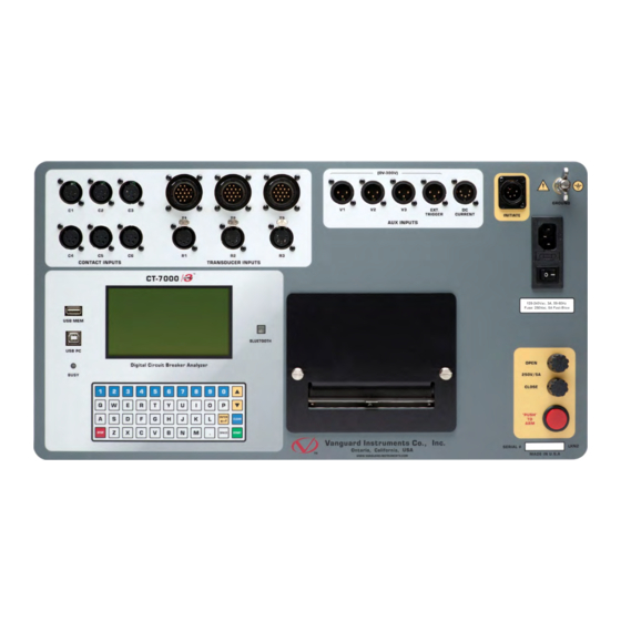
CT-7000 S3 USER’S MANUAL CT-7000 S3 Controls and Indicators The CT-7000 S3’s controls and indicators are shown in Figure 1 below. A leader line with an index number points to each control and indicator, which is cross-referenced to a functional description in Table 2. -
Page 12: Table 2. Functional Descriptions Of Ct-7000 S3 Controls And Indicators
CT-7000 S3 USER’S MANUAL REV 1 Table 2. Functional Descriptions of CT-7000 S3 Controls and Indicators Item Panel Markings Functional Description Number CONTACT INPUT Female connectors for the contact channels. The CT-7000-6 S3 is pictured (C1-C6) with 6 channels. T1, T2, T3 Digital travel transducer channels (16-pin connectors). -
Page 13: Pre-Test Setup
Printer Paper The CT-7000 S3’s built-in thermal printer uses 4.5-inch wide thermal paper for printing test results. To maintain the highest print quality and to avoid paper jams, the use of thermal paper supplied by Vanguard Instruments Company is highly recommended. Additional paper can be ordered from the following sources: Vanguard Instruments Co, Inc. - Page 14 CT-7000 S3 USER’S MANUAL REV 1 Replacing the Thermal Printer Paper The roll of thermal paper is housed inside a dispenser underneath the printer cover. To replace the paper, follow the steps below: • Unscrew the two large printer cover screws and remove the printer cover.
-
Page 15: Operating Procedures
REV 1 CT-7000 S3 USER’S MANUAL OPERATING PROCEDURES Cable Connections 3.1.1. Contact Cable Connections A typical contact cable connection to a circuit breaker is shown in Figure 2. Red and black clips are connected across the circuit contact phases A, B, and C. A typical circuit breaker with series contacts is shown in Figure 3. -
Page 16: Figure 3. Typical Connections For Series Contact Circuit Breaker
CT-7000 S3 USER’S MANUAL REV 1 Figure 3. Typical Connections for Series Contact Circuit Breaker... -
Page 17: Initiate Cable Connections
CT-7000 S3 USER’S MANUAL 3.1.2. Initiate Cable Connections The CT-7000 S3 can trip or close breakers through a solid-state device operating on any AC or DC control voltage ranging from 10 to 300 Volts. Both the trip and close circuits are protected by 5 Ampere fuses. -
Page 18: Figure 5. Typical Dc Trip And Ac Close Control Circuit Connection
CT-7000 S3 USER’S MANUAL REV 1 Figure 5. Typical DC Trip and AC Close Control Circuit Connection... -
Page 19: Online Timing Connections (With Optional Online Timing Feature)
The CT-7000 S3 On-Line timing mode requires the use of 3 AC current sensors (provided with the Online Timing Option, Part no. 9021-OT) to monitor the contact time phases A, B, and C. -
Page 20: Figure 7. Typical Connections For Optional On-Line Timing Mode
CT-7000 S3 USER’S MANUAL REV 1 Figure 7. Typical Connections for Optional On-line Timing Mode... -
Page 21: Dual Ground Connections (With Optional Dual Ground Feature)
3.1.4. Dual Ground Connections (with optional Dual Ground feature) With the optional dual ground testing mode, the CT-7000 S3 can measure a CB contact time with ground being applied to both sides of the bushings. The clamp-on probe is connected to one side of the CB safety ground straps, and an AC signal is coupled to this strap. -
Page 22: Analog And Digital Voltage Monitoring Connections
CT-7000 S3 USER’S MANUAL REV 1 3.1.5. Analog and Digital Voltage Monitoring Connections The analog voltage input “V1” can monitor a breaker’s DC control voltage during an operation. The analog voltage input records the nominal DC voltage at no load and the minimum DC voltage while the Trip or Close coil is energized. -
Page 23: External Trigger Input Connections
3.1.6. External Trigger Input Connections The External Trigger Mode can be used to start recording data when the CT-7000 S3 senses a voltage. A typical application for the External Trigger Mode is to time a circuit breaker in a Close operation and to start timing only when the Close coil is energized, thus bypassing the 52X relay delay time. -
Page 24: Digital Transducer Connection
CT-7000 S3 USER’S MANUAL REV 1 3.1.7. Digital Transducer Connection A typical digital transducer connection is shown in Figure 11. Figure 11. Typical Digital Transducer Connection... -
Page 25: Resistor Type Transducer Connection
The CT-7000 S3 provides three channels for resistor type transducers. The transducer resistance input can range from 200 Ohms to 10K Ohms. The CT-7000 S3 supplies a 5 Vdc reference voltage to power the resistor type transducer. The sense voltage is translated into a travel distance based on the transducer calibration parameters. -
Page 26: Changing Setup Parameters
CT-7000 S3 USER’S MANUAL REV 1 Changing Setup Parameters 3.2.1. Entering Test Record Header Information You can enter the test record header information before performing tests. The record header includes identifying information such as the company, station, circuit, model number, etc. Once the header information has been entered, it will apply to all subsequent test records. - Page 27 REV 1 CT-7000 S3 USER’S MANUAL d. The following screen will be displayed: STATION: ↑↓ to position "ENTER" TO ACCEPT [ENTER] Type the station name using the keypad and then press the key. e. The following screen will be displayed: CIRCUIT: ↑↓...
- Page 28 CT-7000 S3 USER’S MANUAL REV 1 h. The following screen will be displayed: SERIAL NUMBER: ↑↓ to position "ENTER" TO ACCEPT [ENTER] Type the circuit breaker serial number using the keypad and then press the key. i. The following screen will be displayed: OPERATOR: ↑↓...
-
Page 29: Setting The Clock
REV 1 CT-7000 S3 USER’S MANUAL 3.2.2. Setting the Clock Follow the steps below to set the CT-7000 S3’s internal clock: a. Start from the “START-UP” menu: 1. TIME BREAKER 09/12/13 2. GET RESULTS 10:10:10 3. SAVE/RESTORE 4. SETUP 5. DIAGNOSTICS Press the key (SETUP). -
Page 30: Configuring Automatic Or Manual Printing Of Test Results
REV 1 3.2.3. Configuring Automatic or Manual Printing of Test Results The CT-7000 S3 can be configured to print graphs and tabulated results automatically or manually after each test. To configure the printing method: a. Start from the “START-UP” menu: 1. -
Page 31: Setting The Units Of Measure
CT-7000 S3 USER’S MANUAL 3.2.4. Setting the Units of Measure The CT-7000 S3 supports and displays both English and Metric calculations. You can switch between the English and Metric systems using the steps below: a. Start from the “START-UP” menu: 1. -
Page 32: Setting The Open Timing Analysis Points
CT-7000 S3 USER’S MANUAL REV 1 3.2.5. Setting the OPEN Timing Analysis Points Two analysis points are used to calculate the velocity of the circuit breaker in the OPEN operation. To configure the OPEN timing analysis points: a. Start from the “START-UP” menu: 1. - Page 33 REV 1 CT-7000 S3 USER’S MANUAL Percentage of stroke is the distance based upon the percentage of the total breaker’s stroke distance. The distance is always measured from the starting point at the fully closed position of the breaker contacts.
- Page 34 CT-7000 S3 USER’S MANUAL REV 1 e. The following screen will be displayed: OPEN ANALYSIS PT 2 1. PERCENT OF STROKE 2. DIST FROM CLOSE 3. CONTACT +/- TIME 1. PERCENT OF STROKE Press the key (PERCENT OF STROKE) to set the open analysis point #2 as a percentage of the total stroke value.
-
Page 35: Selecting The Contact Cycle Reading Frequency
• For complex velocity calculations, the user can create a test plan using the included CT-7000 S3 Breaker Analysis PC Software. The test plan can then be downloaded to the CT-7000 S3 and recalled before running timing tests. - Page 36 CT-7000 S3 USER’S MANUAL REV 1 The contact time is printed on the tabulated test results printout in both milliseconds and cycles. The cycle readings can be in 50 Hz or 60 Hz. You can select the preferred frequency using the steps below: a.
- Page 37 60 hz set Press any key to return to the “START-UP” menu. Sample tabulated test results are shown in Figure 13 and Figure 14. If the frequency value is changed, the cycle values are automatically re- calculated by the CT-7000 S3. NOTE...
-
Page 38: Figure 13. Typical 50 Hz Tabulated Test Results
CT-7000 S3 USER’S MANUAL REV 1 Frequency Set to 50 Hz Cycle readings at 50 Hz Figure 13. Typical 50 Hz Tabulated Test Results Frequency set to 60 Hz Cycle readings at 60 Hz Figure 14. Typical 60 Hz Tabulated Test Results... -
Page 39: Configuring The Channel Settings
CT-7000 S3 USER’S MANUAL 3.2.7. Configuring the Channel Settings The CT-7000 S3 is available with 3 or 6 contact inputs. Since most common timing applications require the use of only 3 contact timing channels and one travel transducer channel, there is no need to print data for more than 3 timing channels and one transducer channel on the graphic and tabulated reports. - Page 40 CT-7000 S3 USER’S MANUAL REV 1 Press either the key (3 CONTACTS) or the key (6 CONTACTS) to select the corresponding number of contact channels. d. The following screen will be displayed: 1. transducer 1 2. transducers 1,2 3. transducers 1,2,3...
-
Page 41: Configuring The Contact Filter Settings
The value can be between 1 and 300. A filter setting of 1 allows the CT-7000 S3 to pick up the first contact transition time after the resistor contact activity is detected. A filter setting of 300 allows the CT-7000 S3 to pick up the last contact transition time after the resistor contact activity is detected. -
Page 42: Figure 15. Contact Filter Setting Illustrations
CT-7000 S3 USER’S MANUAL REV 1 Filter Setting @ 1 will select this contact time Filter Setting @ 300 will select this contact time Filter Setting @ 1 will select this contact time Filter Setting @ 300 will select this contact time... -
Page 43: Configuring The Transducer Encoder Filter Setting
CT-7000 S3 USER’S MANUAL 3.2.9. Configuring the Transducer Encoder Filter Setting In a typical 1-second timing record, the CT-7000 S3 records 20,000 data points for each of the contact channels, digital transducer channels, voltage input channels, CT channel, DCR channel, resistor transducer channel, and initiate current channel. - Page 44 The following screen will be displayed: ENTER FILTER TIME (010 - 999) [ENTER] Type the filter time (in milliseconds) using the keypad, and then press the to return to the “START-UP” menu. The CT-7000 S3 will not record any transducer encoder data after this time.
-
Page 45: Configuring The Digital Rotary Transducer Settings
REV 1 CT-7000 S3 USER’S MANUAL 3.2.10. Configuring the Digital Rotary Transducer Settings A rotary transducer requires the user to enter the defined linear distance in millimeters or inches per one degree of rotary motion. Follow the steps below to configure the settings for a digital rotary transducer: a. - Page 46 CT-7000 S3 USER’S MANUAL REV 1 1. ENGLISH (In./deg) Press the key to enter the rotary encoder linear distance per degree using English units (inches per degree). The following screen will be displayed: inches/degree 1.442 in/deg [CLEAR] Type the desired value using the keypad. You can press the...
-
Page 47: Configuring The Resister Type Transducer Settings
The CT-7000 S3 provides three resistor type transducer channels. The transducer must be configured before it can be used with the CT-7000 S3. Up to 9 resistor transducer setups can be stored in the CT-7000 S3’s Flash EEPROM. When a resistive transducer is used with the CT-7000 S3, it is shown as transducer #1 on the timing report as shown in Figure 17. - Page 48 CT-7000 S3 USER’S MANUAL REV 1 d. The following screen will be displayed: RESISTIVE ENCODER: 1. CREATE NEW SETUP 2. LOAD SETUP 3. PRINT SETUP DIR Press the key (CREATE NEW SETUP). e. The following screen will be displayed: RESISTIVE ENCODER: 1.
- Page 49 REV 1 CT-7000 S3 USER’S MANUAL h. The following screen will be displayed (the units of measure displayed will depend on your choice in step e): ENTER THE DISTANCE MOVED: "ENTER TO CONTINUE" Enter the distance the transducer was moved using the keypad, and then press the [ENTER] key.
- Page 50 CT-7000 S3 USER’S MANUAL REV 1 l. The setup will be saved and the following confirmation screen will be displayed: SETUP SAVED! Press any key to return to the “START-UP” menu. Loading a Resistor Type Transducer Setup Follow the steps below to load a resistor type transducer setup: a.
- Page 51 REV 1 CT-7000 S3 USER’S MANUAL d. The following screen will be displayed: RESISTIVE ENCODER: 1. CREATE NEW SETUP 2. LOAD SETUP 3. PRINT SETUP DIR Press the key (LOAD SETUP). e. The following screen will be displayed: ENTER SETUP NUMBER TO LOAD (1-9) Type the setup number to load using the numeric keypad.
- Page 52 CT-7000 S3 USER’S MANUAL REV 1 Printing a Resistor Type Transducer Setup Directory You can print a directory of the stored resistor type transducer setups on the built-in thermal printer using the steps below: a. Start from the “START-UP” menu: 1.
-
Page 53: Figure 16. Sample Resistor Type Transducer Setup Directory
REV 1 CT-7000 S3 USER’S MANUAL Figure 16. Sample Resistor Type Transducer Setup Directory... -
Page 54: Figure 17. Sample Timing Report Using A Resistor Type Transducer
CT-7000 S3 USER’S MANUAL REV 1 Resistive Type Transducer Indicator Figure 17. Sample Timing Report Using a Resistor Type Transducer... -
Page 55: Performing Circuit Breaker Timing Tests
REV 1 CT-7000 S3 USER’S MANUAL Performing Circuit Breaker Timing Tests The CT-7000 S3 can initiate the breaker operation and perform a timing test on the following operations: • OPEN • CLOSE • OPEN-CLOSE • CLOSE-OPEN • OPEN-CLOSE-OPEN The CT-7000 S3 can start the OPEN-CLOSE operations without a delay or by using a programmable delay between the OPEN and CLOSE commands. -
Page 56: Timing An Open Operation
REV 1 3.3.1. Timing an OPEN Operation The CT-7000 S3 can time breakers with or without insertion resistors. The insertion resistance can range from 10 to 5,000 Ohms. Any insertion resistance greater than 5,000 Ohms is detected as an open circuit. The timing results will show the main contact time and the insertion resistor contact time. - Page 57 REV 1 CT-7000 S3 USER’S MANUAL resistor value: 1. LESS THAN 1000 OHMS 2. 1000 to 2000 OHMS 3. MORE THAN 2000 OHMS Select the resistance value by pressing the corresponding key ( , or Continue to step d. d. The following screen will be displayed: TIMING WINDOW: 1.
- Page 58 “START-UP” menu once testing is finished. • Please see section 3.3.5 for information about printing test results. • The CT-7000 S3 can be configured to print tabulated and graphics reports automatically after performing a test. Please see section 3.2.3 for further NOTES information.
-
Page 59: Timing A Close-Open Operation Using Contact Channel #1
There are three options when timing a CLOSE-OPEN operation: 1. Contact #1 CLOSE The CT-7000 S3 will initiate a CLOSE operation. The open operation is then initiated after contact channel #1 is closed. This option closes simulates the breaker closing on a fault condition in the field. - Page 60 CT-7000 S3 USER’S MANUAL REV 1 c. The following screen will be displayed: INSERTION RESISTOR? 1. NO 2. YES Press the key (NO). d. The following screen will be displayed: TIMING WINDOW: 1. WINDOW = 1 2. WINDOW = 10 SEC 3.
- Page 61 REV 1 CT-7000 S3 USER’S MANUAL g. The following screen will be displayed: C-O SECOND TRIGGER: 1. CONTACT #1 CLOSE 2. SET DELAY 3. NO DELAY Contact #1 CLOSE Press the key if you would like the open operation to be initiated after contact channel #1 is closed.
- Page 62 CT-7000 S3 USER’S MANUAL REV 1 i. The following screen will be displayed: TEST IN PROGRESS HOLD "ARM" UNTIL TEST COMPLETES. (UP TO 25 SECONDS) [ARM] Continue to hold down the switch until testing is finished. You will be returned...
-
Page 63: Timing An Open-Close-Open Operation
REV 1 CT-7000 S3 USER’S MANUAL 3.3.3. Timing an OPEN-CLOSE-OPEN Operation The OPEN-CLOSE-OPEN operation requires the user to enter two time delays (in milliseconds) between the circuit breaker operations. The first delay is from the first OPEN command to the CLOSE command, and the second delay is from the CLOSE command to the second OPEN command. - Page 64 CT-7000 S3 USER’S MANUAL REV 1 e. The following screen will be displayed: TRIGGER MODE: 1. INTERNAL TRIGGER 2. EXTERNAL TRIGGER Press the key (INTERNAL TRIGGER). f. The following screen will be displayed: TIMING MODE: 1. OPEN 2. CLOSE 3. O-C 4.
- Page 65 REV 1 CT-7000 S3 USER’S MANUAL i. The following screen will be displayed: HOLD "ARM" UNTIL TEsT COMPLETES. "START" TO BEGIN "STOP" TO ABORT [ARM] [START] Hold down the switch and press the key. j. The following screen will be displayed: TEST IN PROGRESS HOLD "ARM"...
- Page 66 CT-7000 S3 USER’S MANUAL REV 1 3.3.4. Performing an On-Line Timing Test on Live Contacts The optional "On-line" timing mode (part no. 9021-OT) can be used to capture the breaker's trip or close time, the trip/close coil current “fingerprint”, and the battery supply voltage while the breaker is still in service.
- Page 67 REV 1 CT-7000 S3 USER’S MANUAL Press the key (OPEN). e. The following screen will be displayed: -> NO INITIATE CABLES -> EXTERNAL TRIGGER ONLY! "START" TO BEGIN "STOP" TO ABORT [START] Press the key. f. The following screen will be displayed temporarily: TESTING IN PROGRESS...
-
Page 68: Figure 18. Typical O-C-O Test Results Graph
CT-7000 S3 USER’S MANUAL REV 1 Figure 18. Typical O-C-O Test Results Graph... -
Page 69: Figure 19. Typical Tabulated Test Results Printout For An O-C-O Operation
REV 1 CT-7000 S3 USER’S MANUAL Figure 19. Typical Tabulated Test Results Printout for an O-C-O Operation... -
Page 70: Figure 20. Typical On-Line Timing Test Graph Printout
CT-7000 S3 USER’S MANUAL REV 1 Figure 20. Typical On-Line Timing Test Graph Printout... -
Page 71: Figure 21. Typical On-Line Timing Test Results Printout
REV 1 CT-7000 S3 USER’S MANUAL Figure 21. Typical On-Line Timing Test Results Printout... -
Page 72: Printing Or Viewing Timing Results
CT-7000 S3 USER’S MANUAL REV 1 3.3.5. Printing or Viewing Timing Results Follow the steps below to print or view the timing results after performing a circuit breaker timing test: a. After performing a timing test you will be returned to the “START-UP” menu: 1. - Page 73 REV 1 CT-7000 S3 USER’S MANUAL Press the key (DISPLAY RESULTS) to display the test results on the unit’s LCD screen. The following screen will be displayed: UP / DWN ARROWS TO SCROLL RESULTS... "STOP" TO EXIT... [] [] Press the keys to scroll through the test results.
-
Page 74: Figure 22. Typical Tabulated Test Results Printout For A Close Operation
CT-7000 S3 USER’S MANUAL REV 1 Enter the end point for the expansion by typing the first digit of the 100 millisecond increment. For example, to select 900ms, press the key. The screen will be updated as shown: EXPANSION FROM: 900MS "ENTER"... -
Page 75: Table 3. Descriptions Of Tabulated Test Results Elements
REV 1 CT-7000 S3 USER’S MANUAL Table 3. Descriptions of Tabulated Test Results Elements Item Description Number Test record number and the date and time the test was performed. Test record header information (Company, Station, Circuit, etc.). Type of test performed (OPEN, CLOSE, O-C, C-O, or O-C-O). -
Page 76: Figure 23. Typical Test Results Graph (Cb Close Test)
CT-7000 S3 USER’S MANUAL REV 1 Figure 23. Typical Test Results Graph (CB CLOSE Test) -
Page 77: Figure 24. Expansion Graph From 0Ms To 200Ms (Cb Close Test)
REV 1 CT-7000 S3 USER’S MANUAL Figure 24. Expansion Graph from 0ms to 200ms (CB CLOSE Test) -
Page 78: Figure 25. Typical O-C-O Test Results Graph
CT-7000 S3 USER’S MANUAL REV 1 Figure 25. Typical O-C-O Test Results Graph... -
Page 79: Figure 26. Typical Tabulated Test Results Printout For An O-C-O Operation
REV 1 CT-7000 S3 USER’S MANUAL Figure 26. Typical Tabulated Test Results Printout for an O-C-O Operation... -
Page 80: Figure 27. Graphical Interpretation Of An Open Timing Shot
CT-7000 S3 USER’S MANUAL REV 1 Figure 27. Graphical Interpretation of an OPEN Timing Shot Figure 28. Graphical Interpretation of a CLOSE Timing Shot... -
Page 81: Figure 29. Graphical Interpretations Of An Open-Close And Close-Open Timing Shot
REV 1 CT-7000 S3 USER’S MANUAL Figure 29. Graphical Interpretations of an OPEN-CLOSE and CLOSE-OPEN Timing Shot... -
Page 82: Working With Test Records
REV 1 Working with Test Records 3.4.1. Saving a Timing Record in Flash EEPROM After performing a test, you can store the results in the CT-7000 S3’s Flash EEPROM. To save a test record: a. Start from the “START-UP” menu: 1. -
Page 83: Printing A Directory Of Test Records Stored In The Ct-7000 S3'S Memory
CT-7000 S3 USER’S MANUAL 3.4.2. Printing a Directory of Test Records Stored in the CT-7000 S3's Memory You can print a directory of all the test records stored in the CT-7000 S3’s Flash EEPROM by using the steps below: a. Start from the “START-UP” menu: 1. -
Page 84: Figure 30. Sample Test Record Directory Printout
CT-7000 S3 USER’S MANUAL REV 1 Figure 30. Sample Test Record Directory Printout... -
Page 85: Printing A Directory Of Test Records Stored In A Usb Flash Drive
REV 1 CT-7000 S3 USER’S MANUAL 3.4.3. Printing a Directory of Test Records Stored in a USB Flash Drive To print a directory of all test records stored in a USB Flash drive: a. Make sure the USB Flash drive is inserted in the unit's USB Flash drive port ("USB MEM"... -
Page 86: Recalling A Test Record From The Flash Eeprom
CT-7000 S3 USER’S MANUAL REV 1 3.4.4. Recalling a Test Record from the Flash EEPROM Follow the steps below to recall a test record from the CT-7000 S3’s Flash EEPROM: a. Start from the “START-UP” menu: 1. TIME BREAKER 09/17/13 2. - Page 87 REV 1 CT-7000 S3 USER’S MANUAL e. The following screen will be displayed: RESTORE COMPLETE PRINT RECORD? 1. YES 2. NO Press the key (YES) if you would like to print the restored test record. The following screen will be displayed: 1.
-
Page 88: Restoring A Test Record From A Usb Flash Drive
REV 1 3.4.5. Restoring a Test Record from a USB Flash Drive You can restore a test record from a USB Flash drive to the CT-7000 S3's working memory using the steps below: a. Make sure the USB Flash drive containing the test record(s) is inserted in the CT-7000 S3's USB Flash drive port ("USB MEM"... - Page 89 REV 1 CT-7000 S3 USER’S MANUAL [ENTER] Type the record number that you would like to restore and press the key. If you do not know the record number, you can print a test record directory using the instructions in section 3.4.3.
-
Page 90: Copying Test Records To A Usb Flash Drive
REV 1 3.4.6. Copying Test Records to a USB Flash Drive You can easily copy test records stored in the CT-7000 S3's Flash EEPROM to a connected USB Flash drive using the steps below: a. Make sure a USB Flash drive is inserted in the unit's Flash drive port ("USB MEM" port). - Page 91 REV 1 CT-7000 S3 USER’S MANUAL Type the record number that you would like to copy to the USB Flash drive and then [ENTER] press the key. If you do not know the record number, you can first print a test record directory using the instructions in section 3.4.2.
-
Page 92: Deleting Test Records From The Flash Eeprom
CT-7000 S3 USER’S MANUAL REV 1 3.4.7. Deleting Test Records from the Flash EEPROM You can delete one or all test records stored in the CT-7000 S3’s Flash EEPROM. To delete test records: a. Start from the “START-UP” menu: 1. TIME BREAKER 09/17/13 2. - Page 93 ERASE COMPLETE Press any key to return to the “START-UP” menu. ERASE ALL SHOTS! Press the key to erase all test records from the CT-7000 S3’s Flash EEPROM. The following screen will be displayed: ALL SHOTS WILL BE ERASED! "ENTER" TO CONTINUE...
- Page 94 CT-7000 S3 USER’S MANUAL REV 1 The following screen will be displayed when all the test records have been completely erased: ERASE COMPLETE ANY KEY TO CONTINUE Press any key to return to the “START-UP” menu.
-
Page 95: Deleting Test Records From A Usb Flash Drive
REV 1 CT-7000 S3 USER’S MANUAL 3.4.8. Deleting Test Records from a USB Flash Drive To erase one or all test records stored on a USB Flash drive: a. Make sure a Flash drive is inserted in the unit's Flash drive port ("USB MEM" port). Then start from the "START-UP"... - Page 96 CT-7000 S3 USER’S MANUAL REV 1 ERASE THUMB DRIVE REC_ [ENTER] Type the record number to be deleted and press the key. If you do not know the record number, you can first print a test record directory using the instructions in section 3.4.3.
- Page 97 REV 1 CT-7000 S3 USER’S MANUAL ALL THUMB DRIVE RECORDS ERASED! Press any key to return to the "START-UP" menu.
-
Page 98: Working With Test Plans
The CT-7000 S3 comes with the Vanguard Circuit Breaker Analysis S2 (VCBA S2) PC Software that can be used to create circuit breaker test plans. The test plans can then be transferred to the CT-7000 S3. The CT-7000 S3 can store up to 99 circuit breaker test plans in its Flash EEPROM. - Page 99 3. PRINT PLAN DIR 4. ERASE TEST PLAN 5. SAVE TEST PLAN Press the key (LOAD TEST PLAN). e. The first test plan stored in the CT-7000 S3’s Flash EEPROM will be listed: TEST PLAN # 01 BZO-145-20-7 SIEMENS DEMO TEST PLAN 1 []...
-
Page 100: Figure 31. Typical Test Results Printout With Pass/Fail Indicators
CT-7000 S3 USER’S MANUAL REV 1 NOTE NO TEST PLANS FOUND "ENTER" TO CONINUE [ENTER] Press the key to return to the “START-UP” menu. Pass/Fail Indicators Figure 31. Typical Test Results Printout with Pass/Fail Indicators... -
Page 101: Printing A Directory Of Test Plans Stored In The Ct-7000 S3'S Memory
CT-7000 S3 USER’S MANUAL 3.5.2. Printing a Directory of Test Plans Stored in the CT-7000 S3’s Memory You can print a directory of all the test plans stored in the CT-7000 S3’s Flash EEPROM using the steps below: a. Start from the “START-UP” menu: 1. -
Page 102: Figure 32. Typical Test Plan Directory Printout
CT-7000 S3 USER’S MANUAL REV 1 Figure 32. Typical Test Plan Directory Printout... -
Page 103: Printing A Directory Of Test Plans Stored In A Usb Flash Drive
REV 1 CT-7000 S3 USER’S MANUAL 3.5.3. Printing a Directory of Test Plans Stored in a USB Flash Drive Follow the steps below to print a directory of all test plans stored in a USB Flash drive: a. Make sure a USB Flash drive is inserted in the unit's USB Flash drive port ("USB MEM"... - Page 104 CT-7000 S3 USER’S MANUAL REV 1 e. The following screen will be displayed: 1. INTERNAL DIRECTORY 2. THUMB DRIVE DIR Press the key (THUMB DRIVE DIR). The directory of test plans stored on the USB Flash drive will be printed on the built-in thermal printer and you will be returned to the...
-
Page 105: Printing A Breaker Test Plan Stored In The Ct-7000'S Memory
CT-7000 S3 USER’S MANUAL 3.5.4. Printing a Breaker Test Plan Stored in the CT-7000's Memory Follow the steps below to print a breaker test plan stored in the CT-7000 S3’s Flash EEPROM: a. Start from the “START-UP” menu: 1. TIME BREAKER 09/18/13 2. - Page 106 CT-7000 S3 USER’S MANUAL REV 1 e. The first test plan stored in the CT-7000 S3’s Flash EEPROM will be listed: TEST PLAN # 01 BZO-145-20-7 SIEMENS DEMO TEST PLAN 1 [] [] You can scroll through the list of test plans by pressing the keys.
-
Page 107: Printing A Breaker Test Plan Stored In A Usb Flash Drive
REV 1 CT-7000 S3 USER’S MANUAL 3.5.5. Printing a Breaker Test Plan Stored in a USB Flash Drive Follow the steps below to print a breaker test plan stored in a USB Flash drive: a. Make sure a USB Flash drive is connected to the unit's USB Flash drive port ("USB MEM"... - Page 108 CT-7000 S3 USER’S MANUAL REV 1 1. PRINT INTERNAL TP 2. PRINT FLASH DRV TP Press the key (PRINT FLASH DRV TP). f. The following screen will be displayed: PRINT THUMB DRIVE TP PLAN_ [ENTER] Type the test plan number to be deleted and press the key.
-
Page 109: Copying A Test Plan To A Usb Flash Drive
REV 1 CT-7000 S3 USER’S MANUAL 3.5.6. Copying a Test Plan to a USB Flash drive Follow the steps below to copy a test plan from the unit's internal memory to a connected USB Flash drive: a. Make sure a USB Flash drive is inserted in the unit's USB Flash drive port ("USB MEM"... - Page 110 CT-7000 S3 USER’S MANUAL REV 1 ENTER TP NUMBER TO COPY TO FLASH DRV TP NUMBER: [ENTER] Type the test plan number to copy using the keypad and then press the key. If you do not know the test plan number, you can first print a test plan directory using the instructions in section 3.5.2.
-
Page 111: Figure 33. Typical Breaker Test Plan Printout
REV 1 CT-7000 S3 USER’S MANUAL Velocity Calculation Formula Figure 33. Typical Breaker Test Plan Printout... -
Page 112: Figure 34. Siemens Sps2 121 Close Timing Illustration
CT-7000 S3 USER’S MANUAL REV 1 CLOSE Time Parameters Velocity Calculation Formula Figure 34. Siemens SPS2 121 CLOSE Timing Illustration... -
Page 113: Figure 35. Siemens Sps2 121 Open Timing Illustration
REV 1 CT-7000 S3 USER’S MANUAL OPEN Time Parameters Figure 35. Siemens SPS2 121 OPEN Timing Illustration... -
Page 114: Diagnostics, Verification, And Troubleshooting
DIAGNOSTICS, VERIFICATION, AND TROUBLESHOOTING Performing a Slow-Close Test The CT-7000 S3 offers a unique “Slow-Close” test feature. This test measures the distance a breaker’s contact travels from the fully opened position to the point of contact or “touch” position, and the contact wipe or penetration distance. The test requires the operator to manually jack the breaker’s contact from the fully open position to the fully closed position. -
Page 115: Figure 36. Typical Slow-Close Test Results Printout
REV 1 CT-7000 S3 USER’S MANUAL d. The following screen will be displayed: CONTACT 1: OPEN CONTACT 2: OPEN CONTACT 3: OPEN LIFT TO CLS BRKR NOW Manually start closing the breaker and then press the "ENTER" key. The test results will be printed and you be returned to the “START-UP”... -
Page 116: Performing A Transducer Self-Test
CT-7000 S3 USER’S MANUAL REV 1 Performing a Transducer Self-Test You can check the transducer electronics by connecting the transducer to the CT-7000 S3 and running a transducer self-test using the instructions below: a. Start from the “START-UP” menu: 1. TIME BREAKER 09/19/13 2. - Page 117 REV 1 CT-7000 S3 USER’S MANUAL d. The screen will be updated with the new transducer position information: TRANSDUCER TEST: T1= 5.00 in / 360.0° T2= 0.00 in / 000.0° T3= 0.00 in / 000.0° R1= 0.00 IN R2= 0.00 IN R3= 0.00 IN...
-
Page 118: Testing The Cable Hookups
CT-7000 S3 USER’S MANUAL REV 1 Testing the Cable Hookups You can check the CT-7000 S3 contact cable connections to the circuit breaker using the steps below: a. Start from the “START-UP” menu: 1. TIME BREAKER 09/19/13 2. GET RESULTS 10:10:10 3. - Page 119 REV 1 CT-7000 S3 USER’S MANUAL [START] [STOP] Press the key to retest the cable connections, or press the key to end the test and return to the “START-UP” menu.
-
Page 120: Printing Raw Test Record Data
REV 1 Printing Raw Test Record Data You can print the raw hexadecimal timing data collected by the CT-7000 S3 using the “PRINT DATA” command. This feature is used mainly for factory diagnostic testing. The CT-7000 S3 collects 20,000 data points in the one-second timing window. As a result, each data sample is 0.05 ms apart. -
Page 121: Figure 37. Partial Data Points Printout
REV 1 CT-7000 S3 USER’S MANUAL d. The following screen will be displayed: 1. EVERY POINT 2. EVERY 5 POINTS Press the key to print every data point. The data points will be printed and you will be returned to the “START-UP” menu. -
Page 122: Troubleshooting Guide
A dual operation OPEN-CLOSE or CLOSE-OPEN will result in a 0ms reading. • The CT-7000 S3 contact channels may be damaged or the cables may be bad. Try the “Check Hook-UP” test (see section 4.3). No contact time (0 ms) in CLOSE- •... - Page 123 REV 1 CT-7000 S3 USER’S MANUAL When performing an OPEN-CLOSE • Delay between OPEN to CLOSE is probably too short. Increase the test, the breaker opens but will not delay time. close. No data or erratic reading on travel • Bad transducer. Perform a transducer diagnostic test using the transducer.
-
Page 124: Appendices
CT-7000 S3 USER’S MANUAL REV 1 APPENDICES APPENDIX A – ITE Model 14.4K Circuit Breaker Timing Charts and Reports AP1 = 1.5” Bounce-Back AP2 = 3.5” ITE Model 14.4K Circuit Breaker Timing Charts... - Page 125 REV 1 CT-7000 S3 USER’S MANUAL ITE Model 14.4K Circuit Breaker CLOSE-OPEN Timing Chart...
-
Page 126: Ct-7000 S3 User's Manual Rev
CT-7000 S3 USER’S MANUAL REV 1 ITE Model 14.4K Circuit Breaker CLOSE-OPEN Tabulated Report... - Page 127 REV 1 CT-7000 S3 USER’S MANUAL ITE Model 14.4K Circuit Breaker OPEN-CLOSE Timing Chart...
- Page 128 CT-7000 S3 USER’S MANUAL REV 1 ITE Model 14.4K Circuit Breaker OPEN-CLOSE Tabulated Report...
-
Page 129: Appendix B - Siemens Tcp Breaker Velocity Calculation
REV 1 CT-7000 S3 USER’S MANUAL APPENDIX B – Siemens TCP Breaker Velocity Calculation... -
Page 130: Appendix C - Siemens Sps2 Breaker Velocity Calculation
CT-7000 S3 USER’S MANUAL REV 1 APPENDIX C – Siemens SPS2 Breaker Velocity Calculation... -
Page 131: Appendix D - Ct-7000 S3 Test Plan For Siemens Sps2
REV 1 CT-7000 S3 USER’S MANUAL APPENDIX D – CT-7000 S3 Test Plan for Siemens SPS2... -
Page 132: Appendix E - Ct-7000 S3 Transducer Illustrations
CT-7000 S3 USER’S MANUAL REV 1 APPENDIX E – CT-7000 S3 Transducer Illustrations Linear Transducer on an OCB Rotary Transducer on Alsthom HE 1014 Circuit Breaker... - Page 133 REV 1 CT-7000 S3 USER’S MANUAL Rotary Transducer on ABB HMB Mechanism Rotary Transducer on Federal Pacific Circuit Breaker...
- Page 134 CT-7000 S3 USER’S MANUAL REV 1 Resistor Transducer on Vacuum Circuit Breaker...
-
Page 135: Appendix F - Ct-7000 S3 Accessories
REV 1 CT-7000 S3 USER’S MANUAL APPENDIX F – CT-7000 S3 Accessories ON-LINE DUAL GROUND TIMING PROBES PROBES (3 probes) part no 9021-OT part no 9021-DG LINEAR ROTARY TRANSDUCERS TRANSDUCER WITH 10" part no 9087-UC MAGNETIC 25" part no 9088-UC... - Page 136 CT-7000 S3 USER’S MANUAL REV 1 DOBLE TRANSDUCER ADAPTER Part no 9084-UC The Doble Transducer Adapter can be used to interface any Doble travel transducer to a Vanguard circuit breaker analyzer. Connected to Doble rotary transducer...
- Page 137 1520 S. Hellman Ave • Ontario, CA 91761 • USA Phone: 909-923-9390 • Fax: 909-923-9391 www.vanguard-instruments.com Copyright © 2013 by Vanguard Instruments Company, Inc. CT-7000 S3 User’s Manual • Revision 1.0 • October 2, 2013 • TA...
Need help?
Do you have a question about the CT-7000 S3 and is the answer not in the manual?
Questions and answers