Advertisement
Quick Links
860660202
Rev. B
June 2021
www.commscope.com
1. General product information
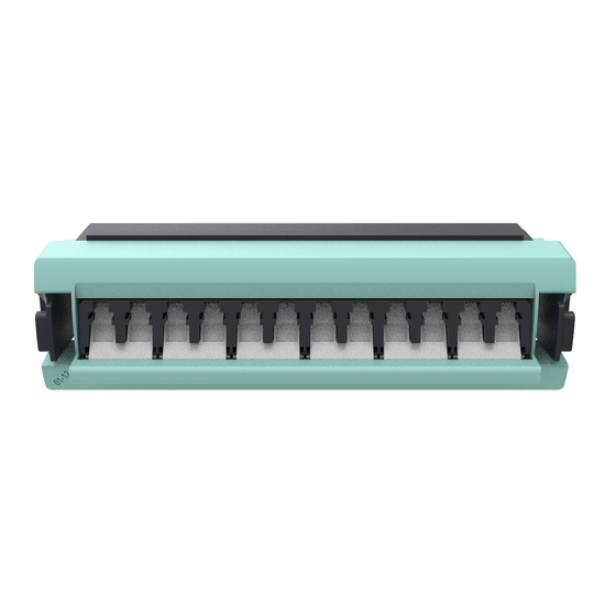
This document provides the installation procedure for the Powered Fiber Cable (PFC) Transition Box (TB). The
TB is designed to facilitate the transition from indoor rated PFC to outdoor rated PFC in a neat and orderly
fashion that maintains physical separation of the different media types. See the
Catalog for available configurations.
2. Tools and additional items required
Round Cable Stripper
•
Electrical Wire Stripper
•
Large Flat Screwdriver
•
Small Flat Screwdriver
•
Power Drill/Driver (as needed)
•
Fiber optic termination and cleaning supplies
•
*CommScope 6 Port Fiber Adaptor in appropriate fiber mode (See Table 1)
•
*CommScope QWIK-FUSE Fiber Field Installable LC Connector Kits in appropriate fiber mode
•
*CommScope Furcation Tubing as required
•
Material ID
Description
760230938
360DPis-12LC-LS
760230946
360DPis-12LC-SM
760230953
360DPis-12LC-MM
760230961
360DPis-12LCA-SM
760236043
360DPis-12LC-WB
760242975
360DPiP-12LC-LS
760242976
360DPiP-12LC-SM
760242977
360DPiP-12LC-WB
760242978
360DPiP-12LCA-SM
Table 1 – Recommended CommScope 6 Port Fiber Adaptors
*Can be ordered from
All trademarks identified by ® or ™ are registered trademarks or trademarks, respectively, of CommScope, Inc. This product may be covered by one or more U.S. patents or
their foreign equivalents. For patents, see www.cs-pat.com. Visit our website at
For technical assistance, customer service, or to report any missing/damaged parts, visit us at:
Powered Fiber Cable Transition Box
Fiber Mode
MM
SM
MM
SM
MM
MM
SM
MM
SM
www.commscope.com
© 2021 CommScope, Inc. All Rights Reserved
Instruction Sheet
Color
AQUA
BLUE
GRAY
GREEN
LIME GRN
AQUA
BLUE
LIME GRN
GREEN
www.commscope.com
or contact your local CommScope representative for more information.
http://www.commscope.com/SupportCenter
CommScope
Product
Page 1 of 9
Advertisement

Subscribe to Our Youtube Channel
Related Manuals for CommScope 760230938


Summary of Contents for CommScope 760230938
- Page 1 Page 1 of 9 All trademarks identified by ® or ™ are registered trademarks or trademarks, respectively, of CommScope, Inc. This product may be covered by one or more U.S. patents or their foreign equivalents. For patents, see www.cs-pat.com. Visit our website at www.commscope.com...
- Page 2 The TB kit contains the plenum rated transition box and cover, plenum rated cable ties, and connectivity label. The G2 6 port fiber adapter can be ordered separately from www.commscope.com. The TB is designed to accommodate up to six (6) PFC channels, with each channel consisting of two power conductors (+ and -) and one duplex fiber connection (TX/TR).
-
Page 3: Installation Steps
4. Insert the 6 port fiber adapter into the G2 opening with the shutters facing in the direction of the terminal strip, as shown in Figure 3. Mounting Knockouts Terminal Strip 6 Port Fiber Adapter Ground Screw Mounting Knockouts Figure 1 Figure 2 Figure 3 © 2021 CommScope, Inc. All Rights Reserved Page 3 of 9... - Page 4 25mm of jacket extending inside the box, as shown in Figure 5. Trim any strength members or other cable components except for power conductors and fibers. APPROX. 25mm OF CABLE JACKET Figure 4 Figure 5 © 2021 CommScope, Inc. All Rights Reserved Page 4 of 9...
- Page 5 Clean and install the LC terminations into the adapter; see installation and cleaning instructions: TECP-96-194. Store excess fiber on the spool, as shown in Figure 8. 8. Repeat steps 1 – 5 for all incoming PFCs. Figure 7 Figure 6 © 2021 CommScope, Inc. All Rights Reserved Page 5 of 9...
- Page 6 Figure 10. Note: Polarization indentation along one side of the cable for polarity identification © 2021 CommScope, Inc. All Rights Reserved Page 6 of 9...
- Page 7 TECP-96-194. Store excess fiber slack on the spool, as shown in Figure 11. 6. Repeat steps 1 – 5 for all outgoing PFCs. Figure 10 Figure 9 Figure 11 © 2021 CommScope, Inc. All Rights Reserved Page 7 of 9...
-
Page 8: Revision History
Place the cover over the loose screw heads with the warning label facing outward and slide into place, tighten the cover screws to secure, as shown in Figure 12. Figure 12 Revision history Rev. A – Initial release • Rev. B – 40132706CMO • © 2021 CommScope, Inc. All Rights Reserved Page 8 of 9... - Page 9 860660202 Rev. B www.commscope.com Instruction Sheet © 2021 CommScope, Inc. All Rights Reserved Page 9 of 9...
Need help?
Do you have a question about the 760230938 and is the answer not in the manual?
Questions and answers