
Subscribe to Our Youtube Channel
Related Manuals for CommScope LSX-288


Summary of Contents for CommScope LSX-288
- Page 1 LGX-Compatible (LSX) 288-Position Termination With Splicing Module User Manual ADCP-93-103 Issue 3 November 2016 23202-A ADCP-93-103 Rev B...
- Page 2 Contents herein are current as of the date of publication. CommScope reserves the right to change the contents without prior notice. In no event shall CommScope be liable for any damages resulting from loss of data, loss of use, or loss of profits and CoommScope further disclaims any and all liability for indirect, incidental, special, consequential or other similar...
-
Page 3: Table Of Contents
CUSTOMER INFORMATION AND ASSISTANCE ........... 18 Page iii © 2017 CommScope. All Rights Reserved. - Page 4 ADCP-93-103 • Issue 3 • November 2016 • Preface Page iv...
-
Page 5: About This Manual
ADCP-93-103 • Issue 3 • November 2016 ABOUT THIS MANUAL This manual describes and provides operating instructions for the LGX-Compatible (LSX) 288- Position Termination With Splicing panel, for the sake of brevity also called the “LSX-288 termination with splicing panel.” ADMONISHMENTS Important safety admonishments are used throughout this manual to warn of possible hazards to persons or equipment. -
Page 6: List Of Acronyms And Abbreviations
The acronyms and abbreviations used in this manual are detailed in the following list: American Wire Gauge Centigrade Distribution Intercept Digital Subscriber Line DSLAM Digital Subscriber Line Access Multiplexer Fahrenheit Monitor POTS Plain Old Telephone Service Page vi © 2017 CommScope. All Rights Reserved. -
Page 7: Description
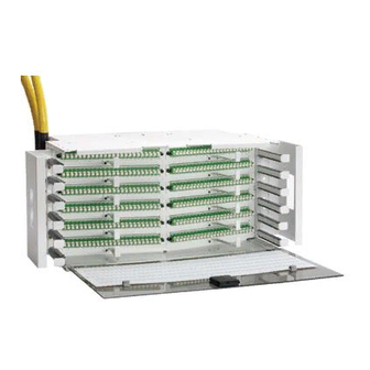
The panel is 11 inches (27.9 cm) high. Five panels fit on a standard 7 foot (2.1 m) frame. 23202-A Figure 1. LSX 288-Position Termination With Splicing Panel Page 1 © 2017 CommScope. All Rights Reserved. -
Page 8: Product Function
MASS FUSION SPLICE CHIP SPLICE TRAY ACCESS DOOR OSP OR IFC CABLE INTERNAL PIGTAILS 23203-A Figure 2. Functional Components of LSX Termination With Splicing Panel (Cut-Away Top View) Page 2 © 2017 CommScope. All Rights Reserved. -
Page 9: Main Components
• Patch Cord Designation Card—is used to record patch cord usage. • Patch Cord Guides—provide cable management in routing patch cords. • Mounting Bracket—is designed for 23-inch rack mount. • Splice Tray Access Door—provides access to rear splice area. Page 3 © 2017 CommScope. All Rights Reserved. - Page 10 Each panel is shipped with a cable clamp as well as vertical cable guides and cable shields (two of each, not shown). Accessories available for the panel include patch cords, heatshrink- or mass-fusion splice chips, and cable clamps (if additional clamps are needed). Page 4 © 2017 CommScope. All Rights Reserved.
-
Page 11: Dimensions
21.46 IN. (54.5 CM) 18.60 IN. (47.2 CM) 9.99 IN. (25.4 CM) 4.78 IN. (12.1 CM) TOP VIEW 10.92 IN. (27.7 CM) 23209-A FRONT VIEW Figure 5. Panel Dimensions Page 5 © 2017 CommScope. All Rights Reserved. -
Page 12: Specifications
For instructions, refer to the following subsections. Mounting the Panel on the Frame Install the panel from the front side of the rack, using the following procedure. Refer to Figure Page 6 © 2017 CommScope. All Rights Reserved. - Page 13 2. Install the VCGs and cable shields using the three small screws provided to secure them to the three small holes in the mounting bracket. 3. Determine the mounting location for the panel. 4. Secure the mounting brackets to the rack front flange using eight #12-24 mounting screws. Page 7 © 2017 CommScope. All Rights Reserved.
-
Page 14: Breaking Out A Cable
Figure 7. Recommended Breakout Dimensions for Ribbon Cable IFC STRANDED CABLE SUBUNIT BREAKOUT LENGTH 94 IN. (238.76 CM) EXPOSED LENGTH 12 IN. (30.48 CM) 23258-A Figure 8. Recommended Breakout Dimensions for Ribbon Cable Page 8 © 2017 CommScope. All Rights Reserved. -
Page 15: Installing A Cable Clamp
SCREW (2) CABLE CLAMP BRACKET MOUNTING HOLES (2) STANDOFF FOR UNDER FLOOR SCREW (2) CABLE CABLE ENTRY) ENTRY HOLE 23248-A CABLE CLAMP BRACKET (OVERHEAD CABLE POSITION) Figure 9. Installing a Cable Clamp Page 9 © 2017 CommScope. All Rights Reserved. -
Page 16: Cable Routing Within Panel
2. Loop the cable clockwise around the splice tray as shown in Figure 3. Tie down the cable at the point where the exposed ribbon cable emerges from the protective tube per the breakout dimensions provided in Topic 3.2. Page 10 © 2017 CommScope. All Rights Reserved. - Page 17 ADCP-93-103 • Issue 3 • November 2016 TIE-OFF POINTS 23257-A Figure 11. Cable Entry From Top TIE-OFF POINTS 23255-A Figure 12. Cable Entry From Bottom Page 11 © 2017 CommScope. All Rights Reserved.
-
Page 18: Patch Cord Routing
To remove the cover, lift it straight out of the hinges. To replace a cover, position the hinge edge of the cover on the hinges and press inward to push the edge into the hinges. Page 12 © 2017 CommScope. All Rights Reserved. -
Page 19: Selecting Patch Cord Length
This practice also prevents dirt particles from entering the adapter or connector. Whenever patch cords are installed, route them down and to the side, as shown in Figure 23247-A RADIUS PATCH CORD CONNECTOR LIMITER GUIDE PACK Figure 14. Correct Routing of Patch Cords Page 13 © 2017 CommScope. All Rights Reserved. -
Page 20: Cross-Connecting Within A Stand-Alone Bay
IN UPPER HALF OF BAY 23244-A 23236-A CONNECTING PORTS SINGLE BAY, ON THE SAME SIDE OPPOSITE SIDES OF A SINGLE BAY OF SAME BAY Figure 15. Routing Patch Cords on a Stand-Alone Bay Page 14 © 2017 CommScope. All Rights Reserved. -
Page 21: Cross-Connecting Between Two Or More Bays
VERTICAL UPPER VERTICAL UPPER VERTICAL TROUGH RACEWAY TROUGH RACEWAY TROUGH 23237-A SAME BAY WITHIN A MULTIBAY LINE-UP Figure 16. Routing Patch Cords Between Adjacent Bays Page 15 © 2017 CommScope. All Rights Reserved. - Page 22 ADCP-93-103 • Issue 3 • November 2016 VERTICAL UPPER VERTICAL UPPER VERTICAL TROUGH RACEWAY TROUGH RACEWAY TROUGH 23238-A 23242-A 23243-A Figure 17. Alternate Paths for Patch Cords Between Adjacent Bays Page 16 © 2017 CommScope. All Rights Reserved.
-
Page 23: Interconnect Procedures
18. Take up slack using the vertical trough as shown in the figure. TO FOT EQUIPMENT OVERHEAD CABLING 23245-A OVER RAISED FLOOR CABLING TO FOT EQUIPMENT Figure 18. Routing Patch Cords Between Adjacent Bays Page 17 © 2017 CommScope. All Rights Reserved. -
Page 24: Customer Information And Assistance
ADCP-93-103 • Issue 3 • November 2016 5 CUSTOMER INFORMATION AND ASSISTANCE http://www.commscope.com/SupportCenter Page 18...
Need help?
Do you have a question about the LSX-288 and is the answer not in the manual?
Questions and answers