DoorHan PCB-SH Programming Instructions Manual
Control board
Hide thumbs
Also See for PCB-SH:
- Programming instructions manual (14 pages) ,
- Programming instructions manual (12 pages)
Table of Contents
Advertisement
Available languages
Available languages
ПЛАТА УПРАВЛЕНИЯ PCB-SH
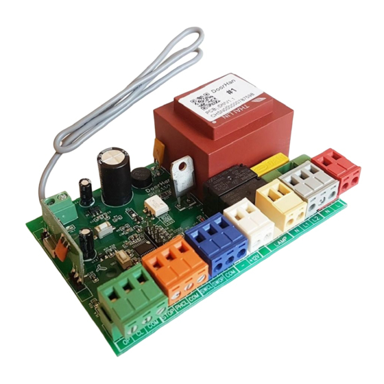
CONTROL BOARD PCB-SH
Актуально для версий
ПО — 1.0–1.1
ПЛАТА — 1.1
Руководство по программированию платы PCB-SH
Programming instructions board PCB-SH
© DoorHan 08.17
Actual versions
soft — 1.0–1.1
pcb — 1.1
ЭЛЕКТРИЧЕСКИЕ ПОДКЛЮЧЕНИЯ
ПРОГРАММИРОВАНИЕ ПРИВОДА
ПРОГРАММИРОВАНИЕ ПУЛЬТОВ ДУ
ELECTRICAL CONNECTIONS
DRIVE PROGRAMMING
PROGRAMMING OF CONTROL PANELS
3
6
7
8
11
12
Advertisement
Table of Contents

Related Manuals for DoorHan PCB-SH


Summary of Contents for DoorHan PCB-SH
- Page 1 DRIVE PROGRAMMING PROGRAMMING OF CONTROL PANELS ПЛАТА УПРАВЛЕНИЯ PCB-SH CONTROL BOARD PCB-SH Актуально для версий Actual versions ПО — 1.0–1.1 soft — 1.0–1.1 ПЛАТА — 1.1 pcb — 1.1 Руководство по программированию платы PCB-SH Programming instructions board PCB-SH © DoorHan 08.17...
-
Page 2: Table Of Contents
3.4. Удаленное программирование пультов DoorHan ........ -
Page 3: Электрические Подключения
ЭЛЕКТРИЧЕСКИЕ ПОДКЛЮЧЕНИЯ 1. ЭЛЕКТРИЧЕСКИЕ ПОДКЛЮЧЕНИЯ 1.1. СХЕМА БЛОКА УПРАВЛЕНИЯ ВНИМАНИЕ! Провода должны быть защищены от контакта с любыми шероховатостями и острыми деталями. Все подключения необходимо проводить только при выключенном питании. ВНИМАНИЕ! Если к клеммам STOP и PH CL не подключены устройства безопасности, установите между общим и... -
Page 4: Описание Клемм Блока Управления
ЭЛЕКТРИЧЕСКИЕ ПОДКЛЮЧЕНИЯ 1.2. ОПИСАНИЕ КЛЕММ БЛОКА УПРАВЛЕНИЯ Клеммы Тип Цвет Разъем Подключение устройств № Значение Команда «полное открывание». Замыкание контактов устройства, под- ключенного к этой клемме, приводит к срабатыванию блока управления Open на полное открывание, либо к пошаговому управлению приводом (в зависимости от установленного режима работы) Команда... -
Page 5: Схемы Подключения Аксессуаров
ЭЛЕКТРИЧЕСКИЕ ПОДКЛЮЧЕНИЯ 1.3. СХЕМЫ ПОДКЛЮЧЕНИЯ АКСЕССУАРОВ... -
Page 6: Программирование Привода
ПРОГРАММИРОВАНИЕ ПРИВОДА 2. ПРОГРАММИРОВАНИЕ ПРИВОДА 2.1. ВЫБОР РЕЖИМА РАБОТЫ Выбор режима работы осуществляется нажатием кнопки «Р». Количество нажатий будет соответствовать номеру вы- бранного режима работы: • одно нажатие — первый режим работы; • два нажатия — второй режим работы; • три нажатия — третий режим работы; •... -
Page 7: Программирование Пультов Ду
После включения питания нажмите и удерживайте кнопку записи пультов «SB2» примерно 20 сек., по истечении этого времени индикатор CODE включится на 1 сек., что означает успешное удаление всех записанных в память пультов. 3.2. ЗАПИСЬ ПУЛЬТОВ DOORHAN В ПРИЕМНИК Для записи пульта нажмите и удерживайте в течение 3 сек. кнопку «R». Индикатор Remote загорится постоянным... -
Page 8: Control Unit Diagram
CONTROL UNIT DIAGRAM 1. CONTROL UNIT DIAGRAM 1.1. CONTROL UNIT SCHEMATIC DIAGRAM CAUTION! Wires in the cable shall be protected against contact with any rough and sharp parts. All connections shall be performed only when the power is off. CAUTION! If no devices are connected to PH CL and COM terminal, it is necessary to install a jumper between contacts PH CL and COM. -
Page 9: Control Unit Terminals Description
CONTROL UNIT DIAGRAM 1.2. CONTROL UNIT TERMINALS DESCRIPTION Terminals Type Color Jack Connecting devices № Meaning Full opening command. After closing of contacts of the device connected Open to this terminal, the control unit will trigger either full opening of the door or stepped control of operator (depending on the preset control logic) ХP9 Close command. -
Page 10: Connection Diagrams For Accessories
CONTROL UNIT DIAGRAM 1.3. CONNECTION DIAGRAMS FOR ACCESSORIES Diagram of PCB-SH, 3-position control station, photocells and open pass door sensor Diagram of PCB-SH, 3-position control station, optoelectronic sensors and open pass door sensor... -
Page 11: Remote Controller Programming
REMOTE CONTROLLER PROGRAMMING Diagram of PCB-SH, traffic light and lamp 2. REMOTE CONTROLLER PROGRAMMING 2.1. SELECTING THE OPERATING MODE Selection of operating mode is by pressing of button “P”. Number of clicks will correspond to number of selected operat- ing mode. The Program indicator shows the selected operation mode, the number of flashes corresponds to the number of the... -
Page 12: Configuring Automatic Closing Actuator
10 seconds the indicator will go out and light up for one second to confirm that the panels have been erased from the memory. Release the panel programming button “R”. 3.2. RECORDING OF DOORHAN PANELS IN THE RECEIVER For panel programming press and hold down the “R” button for 3 seconds. The Remote indicator will illuminate solid red. - Page 13 FOR NOTE...
- Page 14 FOR NOTE...
- Page 15 FOR NOTE...
- Page 16 Тел.: +7 495 933-24-00 E-mail: info@doorhan.ru www.doorhan.ru The company DoorHan thanks you for buying our products. We hope you will be satisfied with the quality of our product. If you need any further information about purchasing, distribution and maintenance, contact our regional agents or refer to our central office to the following address:...
Need help?
Do you have a question about the PCB-SH and is the answer not in the manual?
Questions and answers