
Related Manuals for DoorHan SWING-4000


Summary of Contents for DoorHan SWING-4000
-
Page 1: Table Of Contents
General Information Safety Rules Operator Design Installation Limit Switch Adjustment Emergency Release Maintenance Troubleshooting SWING-4000 Operator Owner’s Manual © DoorHan, 07.2019... -
Page 2: General Information
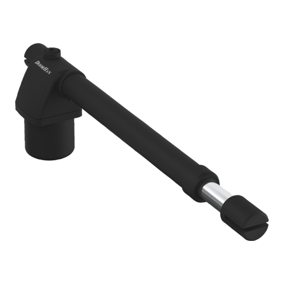
GENERAL INFORMATION 1. GENERAL INFORMATION Swing-4000 electromechanical linear operator is designed to automate a two-wing swing gate with rigid frame. Operator body consists of two silumin parts, in which the gear motor and the lead screw are located. Worm gear and planetary reduction gear form a self-locking system that provides mechanical locking of the gate leaf when the motor is switched off. -
Page 3: Safety Rules
ƒ Carefully follow all the instructions specified herein. Failure to do so could cause equipment damage and/or personal injury. ƒ Swing-4000 is designed to operate swing gates. Use the operator only for its intended purpose, any other use is pro- hibited. -
Page 4: Operator Design
OPERATOR DESIGN 3. OPERATOR DESIGN 1. Motor 3. Rear bracket 5. Housing 2. Power cable 4. Front bracket 6. Limit switches 1175 Unit: mm 4. INSTALLATION 4.1. Tools 1. Set of spanners 4. Set of drills for concrete 7. Electric drill 2. - Page 5 Have a qualified technician lay the 380-400 V AC cables. The cables must be laid in protective corrugated tubes. Avoid contact of cables and moving parts of the gate. In case of supply cable damage, use the suitable type of the cable. Cables necessary for installation of Swing-4000 and accessories (if available): ƒ Cable 2 × 0,5 mm (photocell transmitter, step-by-step control button).
- Page 6 INSTALLATION 4.3.Installation dimensions Column Gate leaf (closed) Hinge Outside property Inside property Opening inwards Opening outwards Gate leaf opening angle А, mm В, mm С, mm D, mm Gate leaf opening angle А, mm В, mm D, mm 1 010 1 010 90°...
- Page 7 INSTALLATION 4.4. Operator installation WARNING! Before installing the operator verify the gate moves smoothly and there is enough space to securely attach the operator to the column and gate leaf. Fasten the rear bracket to the column with anchor bolts. When fastening to a brick column screw anchor bolts into the brick body not in the mortar.
- Page 8 INSTALLATION Brackets mounting angle depends on the gate opening parameters and is adjusted directly at the installation site. 28 mm 68 mm 40 mm Front bracket mounting angle 55 mm 120 mm 60 mm Rear bracket mounting angle...
-
Page 9: Limit Switch Adjustment
LIMIT SWITCH ADJUSTMENT 5. LIMIT SWITCH ADJUSTMENT 5.1. Open position limit switch open position limit switch 1. Release the operator and fully open the gate leaf. 2. Unscrew the mounting screws of the open position limit switch (option). 3. Move the limit switch (option) along the guide until the switch is activated. SwOp LED on the control board will light when the switch is activated. -
Page 10: Maintenance
MAINTENANCE Release Release Engage Engage WARNING! After operator installation is finished test the emergency release system. Unbalanced or damaged gate may cause uncontrolled movement of the operator moving parts when emergency release system is used. 7. MAINTENANCE It is required to carry out regular servicing of the operator in accordance with applicable regulations and legislation, paying ƒ... - Page 11 NOTES...
- Page 12 We very much appreciate that you have chosen the product manufactured by our company and believe that you will be satisfied with its quality. For information on purchasing, distribution and servicing contact DoorHan central office at: 120 Novaya street, Akulovo village, Odintsovo district, Moscow region, 143002, Russia Phone: +7 495 933-24-00 E-mail: info@doorhan.com...
Need help?
Do you have a question about the SWING-4000 and is the answer not in the manual?
Questions and answers