DoorHan PCB-SH Programming Instructions Manual
Control board
Hide thumbs
Also See for PCB-SH:
- Programming instructions manual (14 pages) ,
- Programming instructions manual (16 pages)
Advertisement
Available languages
Available languages
Quick Links
Плата управления
PCB-SH
PCB-SH CONTROL
BOARD
Инструкция по программированию
Programming Instructions
Актуально для версий:
ПО - v 1.0-1.1; плата - v 1.1
© DoorHan, 04.2020
Actual versions:
Soft - v 1.0-1.1; pcb - v 1.1
2
5
5
7
10
10
Advertisement

Related Manuals for DoorHan PCB-SH


Summary of Contents for DoorHan PCB-SH
-
Page 1: Table Of Contents
Программирование привода Программирование пультов ДУ Electrical Connections Operator Programming Transmitter Programming Плата управления PCB-SH PCB-SH CONTROL BOARD Инструкция по программированию Programming Instructions Актуально для версий: Actual versions: ПО — v 1.0-1.1; плата — v 1.1 Soft — v 1.0-1.1; pcb — v 1.1... -
Page 2: Электрические Подключения
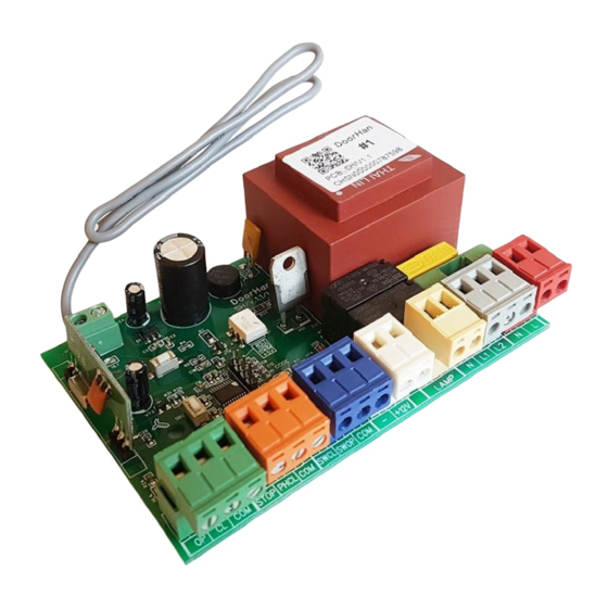
ЭЛЕКТРИЧЕСКИЕ ПОДКЛЮЧЕНИЯ 1. ЭЛЕКТРИЧЕСКИЕ ПОДКЛЮЧЕНИЯ 1.1. СХЕМА БЛОКА УПРАВЛЕНИЯ ВНИМАНИЕ! Провода в кабеле должны быть защищены от контакта с любыми шероховатыми и острыми деталями. Все под- ключения проводите только при выключенном питании. Рис. 1. Электрохема блока управления ВНИМАНИЕ! Если к клеммам STOP и PHCL не подключены устройства безопасности, установите перемычки между общим контактом... - Page 3 ЭЛЕКТРИЧЕСКИЕ ПОДКЛЮЧЕНИЯ Таблица 2. Описание клемм блока управления Клеммы Тип Цвет Разъем Подключение устройств № Значение Команда «полное открывание». Замыкание контактов устройства, под- ключенного к этой клемме, приводит к срабатыванию блока управления Open на полное открывание либо к пошаговому управлению приводом (в зависимости...
- Page 4 ЭЛЕКТРИЧЕСКИЕ ПОДКЛЮЧЕНИЯ Рис. 3. Схема подключения трехпозиционного поста управления, датчика открытой калитки и оптосенсеров Рис. 4. Схема подключения светофора и сигнальной лампы...
-
Page 5: Программирование Привода
После включения питания нажмите и удерживайте кнопку записи пультов «R» примерно 20 сек., по истечении этого времени индикатор «Remote» включится на 1 сек., что означает успешное удаление всех записанных в память пультов. 3.2. ЗАПИСЬ ПУЛЬТОВ DOORHAN В ПРИЕМНИК Для записи пульта нажмите и удерживайте в течение 3 сек. кнопку «R». Индикатор «Remote» загорится постоянным... - Page 6 индикатор «Remote» начнет моргать. Затем нажмите два раза записанную кнопку пульта, который собираетесь удалить из памяти приемника. Индикатор «Remote» выключится. ПРИМЕЧАНИЕ. Для удаления нескольких пультов повторите процедуру для каждого пульта. 3.4. УДАЛЕННОЕ ПРОГРАММИРОВАНИЕ ПУЛЬТОВ DOORHAN Пункты 1–4 необходимо выполнить в пятисекундном интервале. 1. Нажать и удерживать кнопку 2 запрограммированного пульта.
-
Page 7: Electrical Connections
ELECTRIACAL CONNECTIONS 1. ELECTRICAL CONNECTIONS 1.1. CONTROL UNIT SCHEMATIC DIAGRAM WARNING! Cable wires shall be protected against contact with any rough and sharp parts. All connections must be performed only when the power is off. Fig. 1. Control unit wiring diagram WARNING! If no safety devices are connected to PHCL and STOP terminals, then jumper COM terminal and PHCL and STOP con- tacts. - Page 8 ELECTRIACAL CONNECTIONS Table 2. Control unit terminals Terminals Type Colour Jack Connecting devices № Meaning Full opening command. After closing of contacts of the device connected to Open this terminal, the control unit will trigger either full opening of the door or stepped control of operator (depending on the preset control logic) Control devices Green...
- Page 9 ELECTRIACAL CONNECTIONS Fig. 3. Wiring diagram of 3-button control station, optoelectronic sensors and wicket door sensor Fig. 4. Wiring diagram of traffic light and signal lamp...
-
Page 10: Operator Programming
Remote indicator will illuminate for a second to confirm that all the transmitters were erased from the memory. 3.2. RECORDING OF DOORHAN TRANSMITTERS IN THE RECEIVER For transmitter recording press and hold the R button for 3 seconds. The Remote indicator will illuminate solid red. Release the R button. - Page 11 If the function is enabled then the Remote indicator switches on and off once. If the function is disabled then the Remote indicator won't switch on. To enable / disable the function press and hold the R button, then supply power to the control board without releasing the button. 3.6. MARKING OF DOORHAN TRANSMITTERS BUTTONS...
- Page 12 For information on purchasing, distribution and servicing contact DoorHan central office at: 120 Novaya street bld. 1, Akulovo village, Odintsovo district, Moscow region, 143002, Russia Phone: +7 495 933-24-00 E-mail: info@doorhan.com...
Need help?
Do you have a question about the PCB-SH and is the answer not in the manual?
Questions and answers