Renogy REGO Quick Manual
Lithium iron phosphate battery
Hide thumbs
Also See for REGO:
- User manual (101 pages) ,
- Quick manual (48 pages) ,
- User manual (63 pages)
Table of Contents
Advertisement
Quick Links
Advertisement
Table of Contents

Related Manuals for Renogy REGO


Summary of Contents for Renogy REGO
- Page 1 REGO Lithium Iron Phosphate Battery 400Ah VERSION A1 QUICK GUIDE...
-
Page 2: Table Of Contents
Contents Package Contents ....................01 Wiring Diagram ......................02 Product Overview ....................03 Power Connection ....................04 Communication......................07 Turning On ......................10 LED Indicators ....................... 11 Heater Settings ......................14 Turning Off ......................16 Maintenance ......................17... -
Page 3: Package Contents
Package Contents Quick Guide × 1 REGO Lithium Iron Phosphate Battery 400Ah VERSION A0 QUICK GUIDE... -
Page 4: Wiring Diagram
Positive Negative z This Quick Guide contains important installation, operation, and maintenance instructions for the REGO 12V 400Ah Lithium Iron Phosphate Battery. Please read the Quick Guide carefully before using. z Illustrations in the Quick Guide are for reference only. -
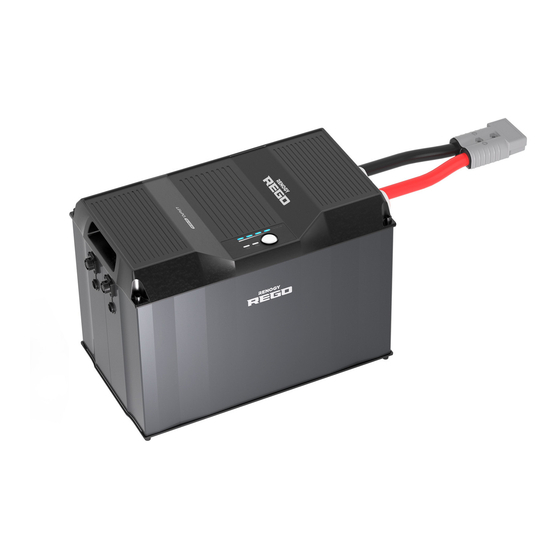
Page 5: Product Overview
Product Overview Part Part Gray Anderson 350 Connector (with Dust Cover) Heater Status Indicator Power Button Battery Level Indicator Battery Status Indicator CAN Communication Ports z Please inspect the battery for any visible damage including cracks, dents, deformation, and other visible abnormalities before installation. -
Page 6: Power Connection
Connecting batteries to the system using the Battery Combiner Box and the System Combiner Box significantly reduces the risk of short circuit, misconnection, or connection failure and allow for quick connection or disconnection. Recommended Accessories REGO 3 Ports 400A Battery REGO 4 Ports 400A System Combiner Box Combiner Box... - Page 7 Anderson connectors or insert terminals on the top of the System Combiner Box. Refer to the user manual of REGO 4 Ports 400A System Combiner Box at renogy. com to confirm what devices the Anderson connectors respectively correspond to.
- Page 8 Power Connection Using Anderson Connector to Ring Terminal Adapter Cables Recommended Accessories Gray Anderson 350 Connector to Positive/Negative Busbars Ring Terminal Adapter Cable z Please ensure equal length of the Adapter Cables to make the batteries operate equally together. z Please size the Busbars appropriately to handle the continuous charge and discharge current of the...
-
Page 9: Communication
Communication The communication connection is optional. It allows the battery to communicate with other REGO devices and monitoring devices, enabling safe operation, smart control, remote monitoring, and programmable settings. Inter-Device Communication Depending on the installation condition, the RV-C communication connections between the battery and other REGO devices can be established with backbone or daisy chain topology. - Page 10 Bluetooth or hard wire, and the Super Panel to the DC Home app through WiFi or cellular network. z Please make sure that the Super Panel is powered on before the connection. z Please read the user manual of Renogy Super Panel at renogy.com before the connection. Recommended Accessories...
- Page 11 If the inter-device communication is established with the daisy chain topology, remove the Terminator Plug from the REGO device at either end of the daisy chain and connect the Super Panel to the free CAN Communication Port on the REGO device with the Communication Adapter Cable (sold separately).
-
Page 12: Turning On
If the battery is unable to be turned on with the Power Button or chargers, please refer to the user manual of the battery on renogy.com for troubleshooting instructions. The Battery Level Indicators light up blue to indicate the current... -
Page 13: Led Indicators
LED Indicators Battery Level Indicators 0%~25% 25.1%~50% 50.1%~75% 75.1%~99.9% 100% 4.1.1 4.1.2 The 4 Battery Level Indicators As the battery charges, the Battery Level Indicators light up blue one respectively indicate 25%, 50%, by one, and the rightmost Battery Level Indicator fast flashes blue to 75%, and 100% battery level. - Page 14 Please refer to the user manual of the battery on renogy.com for the lighting/flashing patterns of the Battery Status Indicator and Heater Status Indicator under different warnings, protections, and permanent failures.
- Page 15 LED Indicators Heater Status Indicator 4.3.1 4.3.2 4.3.3 When the battery temperature When the battery temperature When the battery temperature drops below 41°F, and the charge drops below 41°F, but the charge rises above 50°F, or the charge current is stable and greater than current is unstable or less than current ceases, the heater stops 15A, the heater starts operating,...
-
Page 16: Heater Settings
Heater Settings The battery leaves the factory with the heater enabled. The heater can be enabled or disabled with the Power Button Long press the Power Button for 8 seconds to enter the heater setting mode. The Heater Status Indicator flashes red and green once. - Page 17 Heater Settings z To enable or disable the heaters of the parallel connected batteries simultaneously, please establish the communication connection and enable or disable the heater of any battery with the Power Button. If the communication connection is not established, please enable or disable the heater of each battery individually.
-
Page 18: Turning Off
Turning Off Prior to long periods of storage, please disconnect the battery from the system and turn it off. With the low self-discharge rate when turned off, the battery can hold the charge for a long period of time. Enable/Disable Long press the Power Button for The Battery Level Indicators, All the indicators go out to... -
Page 19: Maintenance
Maintenance Inspection Please perform regular inspections following the steps below. z Examine the external appearance of the battery. The housing and connector contacts of the battery shall be clean, dry, and free of corrosion. z Check the battery cables and connections. Replace any damaged cables and tighten any loose connections. - Page 20 FCC Statement This device complies with Part 15 of the FCC Rules. Operation is subject to the following two conditions: (1) This device may not cause harmful interference, and (2) This device must accept any interference received, including interference that may cause undesired operation.
- Page 21 Renogy Power PLUS Renogy Power Plus allows you to stay in the loop with upcoming solar energy innovations, share your experiences with your solar energy journey, and connect with like-minded people who are changing the world in the Renogy Power Plus community.
- Page 22 RENOGY.COM Visit renogy.com to find the User Manual or get more support via "Contact Us". Renogy reserves the right to change the contents of this manual without notice. Your voice matters! Scan the QR code to submit your feedback on the product.
Need help?
Do you have a question about the REGO and is the answer not in the manual?
Questions and answers