Renogy REGO User Manual
Dc-dc battery charger
Hide thumbs
Also See for REGO:
- User manual (101 pages) ,
- Quick manual (48 pages) ,
- Quick manual (28 pages)
Table of Contents
Advertisement
Quick Links
Advertisement
Table of Contents

Related Manuals for Renogy REGO


Summary of Contents for Renogy REGO
- Page 1 REGO DC-DC Battery Charger VERSION A0 DC-DC Battery Charger USER MANUAL...
- Page 2 Renogy reserves the right to change the information in the user manual without notice. Copyright REGO 12V 60A DC-DC Battery Charger User Manual © 2022 Renogy. All rights reserved. All information in the user manual is subject to copyright and other intellectual property rights of Renogy and its licensors.
-
Page 3: Table Of Contents
Checking the Battery Charger ....................17 Checking Auxiliary Battery ....................18 Automobile Alternator Check ....................19 System Diagram ........................21 Battery Scenario A: REGO Battery Kit ................21 Battery Scenario B: Normal Battery Kit ................23 Battery Charger Wiring ......................24 Auxiliary Battery Wiring ......................26 Battery Scenario A: REGO Battery Kit ................26 Battery Scenario B: Normal Battery Kit ................30... - Page 4 Inter-Device Communication ....................39 Monitoring Device Communication ..................42 Operation ..........................47 Selecting the Battery Type ....................47 Battery Charging Parameters .....................49 User Mode ..........................50 Charging Logic ........................53 LED Indicators ........................55 Battery status ........................55 Fault status .........................55 Troubleshooting ........................56 Maintenance ...........................57 Inspection ...........................57 Cleaning ..........................57 Storage ..........................57 Emergency Responses ......................58 Fire .............................58...
-
Page 5: Important Safety Information
Important Safety Information The user manual provides important installation, operation, and maintenance instructions for REGO 12V 60A DC-DC Battery Charger. Please read the user manual carefully before installation and operation and save it for future reference. Failure to observe the instructions or precautions in the user manual can result in electrical shock, serious injury, or death, or can damage the battery charger, potentially rendering it inoperable. - Page 6 Important Safety Information Symbols Used General Safety Information z Keep the battery charger out of the reach of children. z Please wear proper protective equipment and use insulated tools during installation and operation. z Do not touch the connector contacts when the charger is working. z Please remove all connections before maintenance or cleaning.
-
Page 7: Introduction
Introduction Introduction The Renogy REGO DC-DC Battery Chargers save on installation time than traditional chargers. The pioneering bidirectional charging technology not only provides the most effective way to charge your house batteries from the starter battery on the go but also recharges and maintains your starter battery when the house batteries are full. -
Page 8: Four Charging Stages
Key Features Four Charging Stages Lithium Activation Four Charging Stages REGO 12V 60A DC-DC Battery Charger has a four-stage battery charging algorithm for a rapid, efficient battery charging. They include Bulk Charge, Boost Charge, Float Charge, and Equalization Charge. Battery... -
Page 9: Lithium Activation
Do not equalize VRLA type AGM / Gel / Lithium cell batteries UNLESS permitted by battery manufacturer. z REGO 12V 60A DC-DC Battery Charger provides Equalization charging for flooded batteries by default, with a cycle of once every 30 days. -
Page 10: Package Contents
Package Contents Package Contents REGO 12V 60A Quick Guide x 1 DC-DC Battery Charger x 1 REGO DC-DC Battery Charger VERSION A1 DC-DC Battery Charger DC-DC Battery Charger QUICK GUIDE Renogy Temperature Sensor x 1 IGN Signal Wire x 1... -
Page 11: Optional Accessories
Optional Accessories Optional Accessories Starter Battery Fuse (90A) as input Auxiliary Battery Fuse (80A) as output The battery fuses will protect battery charger, wires and batteries from overcurrent. Fuse Cable The wire is designed with two sections of copper rings, thus enabling the battery charger to function as an external fuse. -
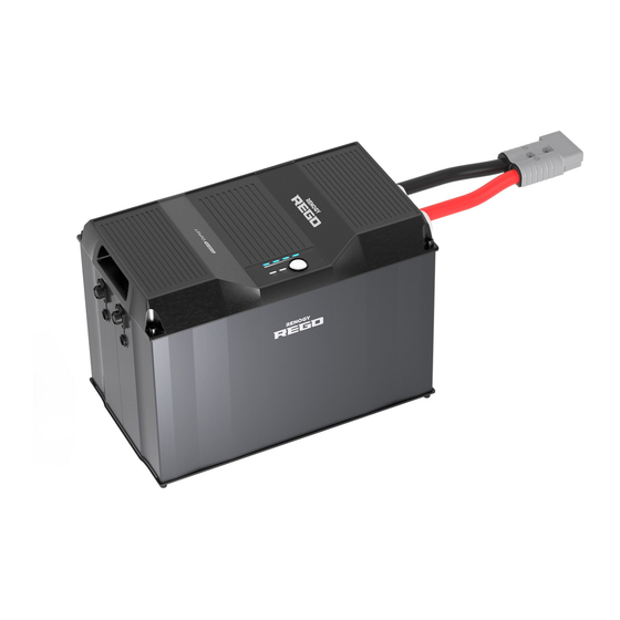
Page 12: Product Overview
Product Overview Product Overview DC-DC Battery Charger BVS BTS input output Part Part Mounting Holes Negative Output Fault Status Indicator Positive Output Battery Status Indicator CAN Communication Ports Battery Type Setting Knob IGN Signal Wire Port Positive Input BVS (Battery Voltage Sensor) Port BTS (Battery Temperature Sensor) Negative Input Port... -
Page 13: Wiring Diagram
Wiring Diagram Wiring Diagram Positive Starter Battery or DC Alternator Auxiliary Battery System Negative... -
Page 14: Recommended Cable Sizing
Recommended Cable Size 0 to 10ft / 0 to 3m 6AWG Input 11 to 20ft / 3 to 6m 6AWG REGO 12V 60A 21 to 30ft / 9 to 6m 4AWG DC-DC Battery Charger 0 to 10ft / 0 to 3m... -
Page 15: Preparation
Components & Tools CAUTION z The adapter cable used in this manual can be made by yourself or purchased from Renogy official website according to the names in Recommended Components. Recommended Components Battery Scenario A: REGO Battery Kit Battery Adapter Cables (input) - Page 16 Preparation Components & Tools Checking the Battery Charger Checking Auxiliary Battery Automobile Alternator Check Battery Scenario B: Normal Battery Kit Battery Adapter Cables (input / output) Normal Battery with +/- Bolts ( Anderson PP75 to Ring Terminal Adapter Cable ) Required Tools Wrench (10mm) Wrench (14mm)
-
Page 17: Checking The Battery Charger
Preparation Components & Tools Checking the Battery Charger Checking Auxiliary Battery Automobile Alternator Check Checking the Battery Charger 1. Please inspect the battery charger for any visible damage including cracks, dents, deformation, and other visible abnormalities. All connector contacts shall be clean, dry, and free of dirt and corrosion. -
Page 18: Checking Auxiliary Battery
Preparation Components & Tools Checking the Battery Charger Checking Auxiliary Battery Automobile Alternator Check 3. Measure the length of the cables connecting to the battery and solar panel so they can be connected to the battery charger. NOTE z If the Battery Adapter Cable or Solar Panel Extension Cable is not long enough, you can use more extension cables or reselect the position where the battery charger needs to be secured. -
Page 19: Automobile Alternator Check
Preparation Components & Tools Checking the Battery Charger Checking Auxiliary Battery Automobile Alternator Check CAUTION z If you replace your battery with a new one, please dispose of the used battery through the specified recycling channel according to the local, state, and federal laws and regulations. WARNING z Do not use the battery charger if it has any visible damage. - Page 20 Preparation Components & Tools Checking the Battery Charger Checking Auxiliary Battery Automobile Alternator Check 1. Locate your main vehicle battery/starter battery. 2. Start the engine, ensuring any fans, radio, and lights. are turned off. Leave the engine running for around 5 to 10 minutes.
-
Page 21: System Diagram
System Diagram Battery Scenario A: REGO Battery Kit Battery Scenario B: Normal Battery Kit System Diagram Battery Scenario A: REGO Battery Kit Using the System Combiner Box Accessory Set Starter Battery or DC Alternator Battery Fuse (90A) REGO 4 Ports 400A... - Page 22 System Diagram Battery Scenario A: REGO Battery Kit Battery Scenario B: Normal Battery Kit Using Positive/Negative Busbars Accessory Set Starter Battery or DC Alternator Battery Fuse (90A) Battery Fuse (80A) Positive/Negative Busbars REGO 12V 400Ah Lithium Positive Iron Phosphate Battery...
-
Page 23: Battery Scenario B: Normal Battery Kit
System Diagram Battery Scenario A: REGO Battery Kit Battery Scenario B: Normal Battery Kit Battery Scenario B: Normal Battery Kit Starter Battery or DC Alternator Battery Fuse (90A) Battery Fuse (80A) Positive Normal Battery with +/- Bolts (12V) Negative... -
Page 24: Battery Charger Wiring
Please refer to the “Recommendations of Wire Diameters and Fuses” in this manual, and select the satisfied cables according to the usage. z Please make sure that the connections of the Anderson connectors are tight and secure. 1. For the Output terminal, REGO Battery Kit input output align the Battery Adapter Cable’s... - Page 25 Battery Charger Wiring 4. For the Input terminal, input align the Battery Adapter Cable’s Anderson PP75 input output connectors to the correct orientation and polarity. 5. Bind the Anderson PP75 connectors by sliding the side grooves. 6. Insert the Anderson PP75 connectors into the Input terminal.
-
Page 26: Auxiliary Battery Wiring
Battery Scenario A: REGO Battery Kit Using the System Combiner Box Accessory Set NOTE z Please read the user manual of REGO 4 Ports 400A System Combiner Box carefully before wiring. █ Using Battery Adapter Cable ( Anderson PP75 to Anderson 120 Adapter Cable ) 1. - Page 27 Auxiliary Battery Wiring Battery Scenario A: REGO Battery Kit Battery Scenario B: Normal Battery Kit Battery Indicator █ Using Battery Adapter Cable ( Anderson PP75 to Ring Terminal Adapter Cable ) NOTE z Select the appropriate wrench according to positive/negative wire fixing bolt specifications of the system hub.
- Page 28 Auxiliary Battery Wiring Battery Scenario A: REGO Battery Kit Battery Scenario B: Normal Battery Kit Battery Indicator Using Positive/Negative Busbars Accessory Set NOTE z Please select the applicable wrench according to wire fixing bolt specifications of Positive/ Negative Busbars. WARNING z Please select the right size of positive/negative sink according to the maximum continuous charging/discharging current of the battery operation.
- Page 29 Auxiliary Battery Wiring Battery Scenario A: REGO Battery Kit Battery Scenario B: Normal Battery Kit Battery Indicator 3. Attach the ring terminal of the negative Battery Adapter Cable (output) to the negative battery DC-DC Battery Charger bolt and tighten it with a wrench.
-
Page 30: Battery Scenario B: Normal Battery Kit
Auxiliary Battery Wiring Battery Scenario A: REGO Battery Kit Battery Scenario B: Normal Battery Kit Battery Indicator Battery Scenario B: Normal Battery Kit NOTE z Please select the appropriate wrench according to the battery positive/negative wire fixing bolt specifications. 1. Attach the ring terminal... -
Page 31: Battery Indicator
Auxiliary Battery Wiring Battery Scenario A: REGO Battery Kit Battery Scenario B: Normal Battery Kit Battery Indicator Battery Indicator Once the battery wiring is completed correctly and the battery is turned on, the battery charger’s Battery indicator lights up green. -
Page 32: Input Wiring
Input Wiring Input Wiring REGO 12V 60A DC-DC Battery Charger can be directly connected to the vehicle’s starter battery (12V). NOTE z Please select the appropriate wrench according to the battery positive/negative wire fixing bolt specifications. z Please ensure that the ring terminals are securely connected. - Page 33 Battery indicator will not flash. REGO 12V 60A DC-DC Battery Charger can be directly connected to the vehicle’s DC alternator (12V). For details, contact our customer service through renogy.com/contact-us/.
- Page 34 Input Wiring WARNING z Identify the polarity (positive and negative) on the cables used for the batteries. A reverse polarity contact may damage the unit. Alternator Recommendation Check your alternator and identify the number of terminals. Most alternator will have 3 wires connected (BAT+, BAT-, and IGN).
- Page 35 Input Wiring Engine Bay Fuse Block Recommendation Review your vehicle’s fuse layout to identify a fuse location that is live when the vehicle is running with the alternator. Key positions in the ignition are typically lock, accessory, on, and start. Off...
-
Page 36: Mounting
Mounting Mounting NOTE z Please make sure that the battery charger is installed firmly to prevent it from falling off. 1. Place the battery charger against a flat surface and secure it with included screws. -
Page 37: Temperature Sensor
Temperature Sensor Temperature Sensor The temperature sensor can detect the battery’s temperature and update it to the battery charger for charging voltage calibration. This ensures the battery charger (with operating temperature range from -20°C to 60°C or -4°F to 140°F) can charge the battery normally. CAUTION z Do not use the temperature sensor on a LiFePO4(LFP) battery which comes with a battery management system(BMS). -
Page 38: Voltage Sensor (Optional)
1. Insert the voltage sensor terminal block to the BVS port. BVS BTS BVS BTS 2. Connect the voltage REGO Battery sensor ring terminal to the positive/negative pole of the battery system. Normal Battery with +/- Bolts... -
Page 39: Communication
Inter-Device Communication Depending on the installation condition, the RV-C communication connections between the battery charger and other REGO devices can be established with backbone or daisy chain topology. The inter-device communication allows the battery charger to dynamically adjust the charging profile for an optimal and safe charge. - Page 40 Communication Inter-Device Communication Monitoring Device Communication Communication z Different drop sockets are used on the RV-C bus by different RV manufacturers. Please select the Drop Plugs that match the drop sockets for the inter-device communication connections. If you are not sure about the Drop Plug selection, please check with the RV manufacturer.
- Page 41 Monitoring Device Communication 4. Connect either of the CAN Communication Ports of the battery charger and other REGO devices to the drop sockets on the drop tap with the Drop Cables. NOTE z Different drop taps are used on the RV-C bus by different RV manufacturers. This User Manual takes the 4-socket drop tap as an example.
-
Page 42: Monitoring Device Communication
CAN Communication Ports on the first and last REGO devices. Monitoring Device Communication The battery charger can be connected to monitoring devices through both short-range and long-range connections. The monitoring device allows for the monitoring and programming of the battery charger or even the complete system. - Page 43 Inter-Device Communication Monitoring Device Communication Long-Range Monitoring If long-range communication and programming are required, connect the battery charger to Renogy ONE through Bluetooth or wires, and the Renogy ONE to the DC Home app through Wi-Fi. Recommended Accessories Renogy ONE NOTE z Please make sure that the Renogy ONE is powered on before the connection.
- Page 44 2 and the white orange CAN_L wire goes to pin 3. Leave pin 1 and pin 4 empty. Connect the RJ45 port of Renogy One to the RV-C bus with the Drop Cable. 12V Power Supply NOTE z Please refer to the Backbone Topology section for more instructions.
- Page 45 Communication Inter-Device Communication Monitoring Device Communication 2. Monitor and program the complete system on Renogy ONE or the DC Home app. 12V Power Supply Recommended Accessories(Daisy Chain Topology) LP16 Plug (7-Pin) to RJ45 Communication Adapter Cable 1. Remove the Terminator...
- Page 46 Communication Inter-Device Communication Monitoring Device Communication 3. Bind Renogy ONE to the DC Home app. Monitor and program the complete system on the Renogy ONE or the DC Home app.
-
Page 47: Operation
Operation Selecting the Battery Type Battery Charging Parameters User Mode Operation Selecting the Battery Type The battery charger is simple and easy to use. The knob with 5 gears makes the selection of battery type more convenient. The default battery type of the battery charger is AGM/SLD. After the wiring of the battery charger output is completed, please manually set the battery type according to needs. - Page 48 Operation Selecting the Battery Type Battery Charging Parameters User Mode 4. If the auxiliary battery is Lithium Battery, turn the knob to LI. DC-DC Battery Charger 5. If multiple parameters of the battery need to be programmed, turn the knob to USER to enter custom mode.
-
Page 49: Battery Charging Parameters
Operation Selecting the Battery Type Battery Charging Parameters User Mode Battery Charging Parameters WARNING z Before modifying battery parameters, please check the table below first. Incorrect parameter setting will damage the device and void the warranty. Battery Type USER USER AGM/SLD FLOODED LI (LFP) -
Page 50: User Mode
Before modifying battery parameters in User mode, please check the table below and consult the battery manufacturer to check whether modification is allowed. Incorrect parameter setting will damage the device and void the warranty. REGO 12V 60A DC-DC Battery Charger Maximum Adjustable Charging Current: Charging Current Max. - Page 51 Operation Selecting the Battery Type Battery Charging Parameters User Mode NOTE z Make sure Bluetooth is turned on. z Please scan the QR Code on the last page of the User Manual to download the DC Home app. z DC Home illustrations in the User Manual are for reference only. Please follow the instructions based on the current app version.
- Page 52 Operation Selecting the Battery Type Battery Charging Parameters User Mode 4. Tap “•••” in the upper right corner. 5. Tap “Settings” to open the mode selection interface. 6. In this interface, you can customize multiple parameters of the battery. When the parameters are modified, “Setting Success”...
-
Page 53: Charging Logic
Charging Logic Charging Logic REGO 12V 60A DC-DC Battery Charger can be charged in two methods. It can be directly connected to the 12V DC Alternator or the 12V starter battery. Different charging methods adapt to more modification situation of users. The charger also supports parallel charging by using two 800W battery chargers to charge the auxiliary battery at the same time. - Page 54 Charging Logic (2) If the voltage is greater than 12V, the auxiliary battery will stop charging the starter battery and activate the standby state. 2. Traditional Alternator: The auxiliary battery will charge the starter battery only when the voltage of the auxiliary battery is greater than 12.7V. The auxiliary charger will charge the starter battery for 1min and then stop charging for 30s.
-
Page 55: Led Indicators
LED Indicators Battery status Fault status LED Indicators Battery status Indicator Color Status Description a. Auxiliary battery full Green b. Float charge c. Standby state Green Flashing The charging battery is charging (1s interval) the Auxiliary battery Not charging Blue The charging battery is charging the starter battery Fault status... -
Page 56: Troubleshooting
Solid Red Auxiliary battery correctly. short circuit 2. If the fault message persists, disable the charger and contact RENOGY. 1. Please check the environment around the charger to ensure that enough space is left for Internal over- Solid Red heat dissipation. -
Page 57: Maintenance
Maintenance Inspection Cleaning Storage Maintenance Inspection For optimum performance, it is recommended to perform these tasks regularly. z Check the appearance of the battery charger to make sure it is clean and dry. z Ensure the battery charger is installed in a clean, dry and ventilated area. z Ensure there is no damage or wear on the cables. -
Page 58: Emergency Responses
Emergency Responses Fire Flooding Smell Noise Emergency Responses In the event of any threat to health or safety, always begin with the steps below before addressing other suggestions. z Immediately contact the fire department or other relevant emergency response team. z Notify all people who might be affected and ensure that they can evacuate the area. -
Page 59: Technical Support
Technical Support Technical Support For additional support, contact the Renogy technical support team through renogy.com/ contact-us. Have the following information available when contacting Renogy. z Owner name z Contact information z Order number z Purchase channel z Serial number z Brief description of the issue Visit renogy.com... -
Page 60: Technical Specifications
Technical Specifications Technical Specifications Parameter Value Model RBC1260DO-12B System Voltage Input Voltage 10V to 16V DC Output Voltage 10V to 16V DC Traditional Alternator: 13.5V to 16VDC Alternator Input Smart Alternator (Euro 6): 12.5V to 16VDC Maximum Output Current Rating Output Power 800W Battery Types... -
Page 61: Dimensions
Dimensions Dimensions 350mm [13.78in] DC-DC Battery Charger 264.5mm [10.41in] 289.5mm [11.4in] 186.67mm [7.35in] input output BVS BTS 102mm [4.02in] 213mm [8.39in] CAUTION z Dimensional tolerance of ± 0.5 mm... - Page 62 FCC Statement This device complies with Part 15 of the FCC Rules. Operation is subject to the following two conditions: (1) This device may not cause harmful interference. (2) This device must accept any interference received, including interference that may cause undesired operation.
- Page 63 "Contact Us". Renogy reserves the right to change the contents of this manual without notice. Manufacturer: RENOGY New Energy Co.,Ltd Address: No.66, East Ningbo Road Room 624-625 Taicang German Overseas Students Pioneer Park...
Need help?
Do you have a question about the REGO and is the answer not in the manual?
Questions and answers