Table of Contents
Advertisement
Quick Links
Advertisement
Table of Contents

Subscribe to Our Youtube Channel
Related Manuals for Renogy REGO RBT12400LFPL-SHBT-US


Summary of Contents for Renogy REGO RBT12400LFPL-SHBT-US
- Page 1 REGO Lithium Iron Phosphate Battery 400Ah VERSION A0 USER MANUAL...
- Page 2 REGO 12V 400Ah Lithium Iron Phosphate Battery (RBT12400LFPL-SHBT) Disclaimer z Renogy makes no warranty as to the accuracy, sufficiency, or suitability of information in the user manual because continuous product improvements are going to be made. z Renogy assumes no responsibility or liability for losses or damages, whether direct, indirect, consequential, or incidental, which might arise out of the use of information in the user manual.
-
Page 3: Table Of Contents
Table of Contents Important Safety Information .......................05 Symbols Used .........................05 General Safety Information .....................05 Introduction ..........................07 Introduction ..........................07 Key Features ...........................07 Package Contents ........................09 Product Overview ........................10 Wiring Diagram ..........................11 Using Combiner Boxes ......................11 Using Busbars .........................11 Installation ...........................12 Inspection ..........................12 Environment ..........................12 Placement ..........................12 Mounting ..........................13... - Page 4 Checking Battery Status ......................30 Checking Heater Status ......................31 Changing Heater Settings .......................33 Charging ..........................34 Discharging ..........................35 Turning Off ..........................35 Maintenance ..........................37 Inspection ..........................37 Cleaning ..........................37 Storage ............................37 Battery Management System ......................39 Warning/Protection/Permanent Failure ...................39 Charge Current Request ......................42 Cell Voltage Balancing ......................42 Troubleshooting ...........................43 Emergency Responses .......................52 Fire ............................52...
-
Page 5: Important Safety Information
Important Safety Information Symbols Used General Safety Information Important Safety Information The User Manual provides important installation, operation, and maintenance instructions for REGO 12V 400Ah Lithium Iron Phosphate Battery. Please read the User Manual carefully before installation and operation and save it for future reference. Failure to observe the instructions or precautions in the User Manual can result in electrical shock, serious injury, or death, or can damage the battery, potentially rendering it inoperable. - Page 6 Important Safety Information Symbols Used General Safety Information CAUTION z Ensure adequate and secure mounting of the battery. z DO NOT expose the battery to strong electrostatic fields, strong magnetic fields, or radiation. z Please use suitable handling equipment for safe transportation of the battery. z Ensure that no water sources are above or near the battery, including downspouts, sprinklers, or faucets.
-
Page 7: Introduction
Introduction Introduction Meet the next era of energy storage system with Renogy 12V 400Ah REGO Lithium Iron Phosphate Battery. With a large capacity of more than 5KWh, the battery is designed to run loads for extended periods of time. Manufactured with top grade cells, the battery provides an exceptional lifespan of more than 3800 cycles (80% DOD), a continuous discharge current up to 350A for heavy loads, and a continuous charge current up to 300A for 1.5-hour fast charging. - Page 8 Introduction Introduction Key Features z RV-C Compatible Allows for complete system integration for better charging experience, safer operation, and more customizable settings with the RV-C protocol compatibility. z Reliable Design Delivers extreme performance even under the harshest conditions with the waterproof die cast aluminum housing.
-
Page 9: Package Contents
Package Contents Package Contents Quick Guide × 1 12V 400Ah REGO Lithium Iron Phosphate Battery × 1 REGO Lithium Iron Phosphate Battery 400Ah VERSION A1 QUICK GUIDE... -
Page 10: Product Overview
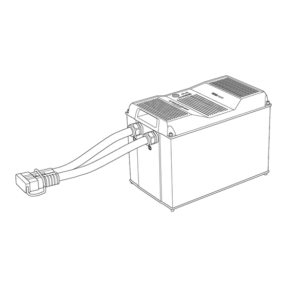
Product Overview Product Overview Part Part Gray Anderson 350 Connector Heater Status Indicator (with Dust Cover) Power Button Battery Level Indicator Battery Status Indicator CAN Communication Ports... -
Page 11: Wiring Diagram
Wiring Diagram Using Combiner Boxes Using Busbars Wiring Diagram Using Combiner Boxes Single Battery DC-DC Inverter Charger DC Distribution Charge System Combiner Box Panel Controller Multiple Batteries DC-DC Inverter Charger DC Distribution Charge Panel Controller Battery System Combiner Combiner Box Positive Negative Using Busbars... -
Page 12: Installation
Installation Inspection Environment Placement Mounting Installation Inspection Inspect the battery for any visible damages including cracks, dents, deformation, and other visible abnormalities before installation. The connector contacts shall be dry, clean, and free of any dirt and corrosion. WARNING z DO NOT use the battery if it appears damaged. Environment Ensure that the installation environment is clean, cool, and well-ventilated. -
Page 13: Mounting
Installation Inspection Environment Placement Mounting CAUTION z DO NOT place the battery upside down or horizontally on the short side. z Ensure that the battery is fully supported. Mounting Recommended Tool and Accessories Phillips Screwdriver Battery Tray Tie Down Strap Mounting Screws 1. - Page 14 Installation Inspection Environment Placement Mounting NOTE z It is recommended to pre-drill holes on the mounting surface with a drill and a drill bit before mounting the Battery Tray. 3. Place the battery into the Battery Tray. Buckle the Tie Down Strap over the battery.
-
Page 15: Power Connection
REGO 3 Ports 400A REGO 4 Ports 400A System Combiner Box Battery Combiner Box(es) INFO z Please read the user manual of REGO 3 Ports 400A Battery Combiner Box and REGO 4 Ports 400A System Combiner Box at renogy.com before the connection. - Page 16 Power Connection Using Combiner Boxes Using Busbars 1. Remove the Dust Covers from the Anderson Connectors. If multiple batteries are to be connected in parallel, refer to step 2 step 4. If only one battery is used, refer to step 2.
- Page 17 Power Connection Using Combiner Boxes Using Busbars 5. If only one battery is used, connect the battery directly to the Anderson connector on the side of the System Combiner Box. 6. Connect the devices to the corresponding Anderson connectors or insert terminals on the top of the System Combiner Box.
-
Page 18: Using Busbars
Power Connection Using Combiner Boxes Using Busbars secured to the proper specification. Using Busbars Required Accessories Gray Anderson 350 Connector to Positive/Negative Busbars Ring Terminal Adapter Cable(s) WARNING z DO NOT short the positive and negative ring terminals of the Adapter Cable(s). Short circuits can damage the battery. - Page 19 Power Connection Using Combiner Boxes Using Busbars WARNING z Please size the Adapter Cable(s) appropriately to handle the expected current. Refer to Appendix for more instructions. CAUTION z If multiple batteries are to be connected in parallel, please ensure equal length of the Adapter Cables to make the batteries operate equally together.
-
Page 20: Communication
Communication Inter-Device Communication Monitoring Device Communication Communication The communication connection is optional. It allows the battery to communicate with other REGO devices and monitoring devices, enabling safe operation, smart control, remote monitoring, and programmable settings. Inter-Device Communication Depending on the installation condition, the communication connections between the battery and other REGO devices can be established with backbone or daisy chain topology. - Page 21 Communication Inter-Device Communication Monitoring Device Communication NOTE z Different drop sockets are used on the RV-C bus by different RV manufacturers. Please select the Drop Plugs that match the drop sockets for the inter-device communication connections. If unsure about the Drop Plug selection, please check with the RV manufacturer.
- Page 22 Communication Inter-Device Communication Monitoring Device Communication 4. Connect either of the CAN Communication Ports of the battery and other REGO devices to the drop sockets on the drop tap with the Drop Cables. Daisy Chain topology If the RV-C bus is not available, follow the daisy chain topology for the inter-device communication connections.
-
Page 23: Monitoring Device Communication
Bluetooth. 1. Open the DC Home app. Turn on the Bluetooth on the phone or tablet. Tap “+” My Renogy on the top right corner to search for the battery. Wait for a few minutes until the battery is found. - Page 24 Long-Range Monitoring If long-range communication and programming are required, connect the battery to Renogy ONE through Bluetooth or hard wire, and Renogy ONE to the DC Home app through WiFi. Required Tool and Accessories LP16 Plug (7-Pin) to RJ45 Communication...
- Page 25 RCC60RVRU Device Scene Community Personal Power Supply NOTE z Please keep Renogy ONE within 10 feet (3 m) of the battery. 3. If the inter-device Backbone Topology communication is established with the backbone topology, replace the terminated drop tap at either end of...
- Page 26 Communication Inter-Device Communication Monitoring Device Communication 4. Monitor and program the complete system on Renogy ONE or the DC My Renogy Home app. h left Commonly Security Night Devices Battery Controller RBT12400LFPL-... RCC60RVRU Device Scene Community Personal Power Supply 5. If the inter-device...
-
Page 27: Commission
Commission Checking Checking Checking Changing Indicator Turning Turning Charging Discharging Battery Level Battery Status Heater Status Heater Settings Pattern Off Commission Indicator Pattern Indicator Pattern 1 Second 1 Second Solid Slow Flash Fast Flash Double Flash Strobe Turning On The battery is off when it leaves the factory. Please turn the battery on after connecting it to the system for the first time. - Page 28 Commission Checking Checking Checking Changing Indicator Turning Turning Charging Discharging Battery Level Battery Status Heater Status Heater Settings Pattern Off 2. The Battery Level Indicators, Battery Status Indicator, and Heater Status Indicator flash in sequence once to indicate that the battery has been Enabled/Disabled turned on.
-
Page 29: Checking Battery Level
Commission Checking Checking Checking Changing Indicator Turning Turning Charging Discharging Battery Level Battery Status Heater Status Heater Settings Pattern Off Checking Battery Level 1. The four Battery Level Indicators respectively indicate 25%, 50%, 75%, and 100% battery level. 100% 2. As the battery charges, the 0%~25% 25.1%~50% Battery Level Indicators... -
Page 30: Checking Battery Status
Commission Checking Checking Checking Changing Indicator Turning Turning Charging Discharging Battery Level Battery Status Heater Status Heater Settings Pattern Off 5. The last Battery Level Indicator slow flashes blue when the battery level drops below 10%. NOTE z The Battery Level Indicators go out when the battery is in the heater setting mode or permanent failure mode. -
Page 31: Checking Heater Status
Commission Checking Checking Checking Changing Indicator Turning Turning Charging Discharging Battery Level Battery Status Heater Status Heater Settings Pattern Off 3. The Battery Status Indicator lights up/flashes red when the battery is in the protection mode. 4. The Battery Status Indicator and Heater Status Indicator flash red simultaneously when the battery is in the permanent failure mode. - Page 32 Commission Checking Checking Checking Changing Indicator Turning Turning Charging Discharging Battery Level Battery Status Heater Status Heater Settings Pattern Off 2. When the battery temperature drops below 41°F (5°C), but the charge current is unstable or less than 15A, or the heater malfunctions, the heater is unable to operate properly, and the Heater Status Indicator lights up red.
-
Page 33: Changing Heater Settings
Commission Checking Checking Checking Changing Indicator Turning Turning Charging Discharging Battery Level Battery Status Heater Status Heater Settings Pattern Off Changing Heater Settings The battery leaves the factory with the heater enabled. The heater can be enabled or disabled with the Power Button. 1. -
Page 34: Charging
Commission Checking Checking Checking Changing Indicator Turning Turning Charging Discharging Battery Level Battery Status Heater Status Heater Settings Pattern Off 3. Long press the Power Button for 8 seconds to exit the heater setting mode and save the current setting. The Heater Status Indicator flashes red and green once. -
Page 35: Discharging
Commission Checking Checking Checking Changing Indicator Turning Turning Charging Discharging Battery Level Battery Status Heater Status Heater Settings Pattern Off CAUTION z DO NOT overcharge the battery. z DO NOT exceed the maximum continuous charge current of the battery. z Please charge the battery with the chargers (not included) that are compatible with the lithium iron phosphate battery and the charge voltage set at 14.4V. - Page 36 Commission Checking Checking Checking Changing Indicator Turning Turning Charging Discharging Battery Level Battery Status Heater Status Heater Settings Pattern Off 1. Long press the Power Button for 3 seconds. 2. The Battery Level Indicators, Battery Status Indicator, and Heater Status Indicator fast flash simultaneously to indicate that the battery is turning off.
-
Page 37: Maintenance
Maintenance Inspection Cleaning Storage Maintenance Inspection Please perform regular inspections following the steps below. z Examine the external appearance of the battery. The housing and connector contacts of the battery shall be clean, dry, and free of corrosion. z Check the battery cables and connections. Replace any damaged cables and tighten any loose connections. - Page 38 Maintenance Inspection Cleaning Storage CAUTION z DO NOT expose the battery to extreme temperatures above 140°F (60°C). z DO NOT expose the battery to heat sources. z DO NOT expose the battery to direct sunlight, moisture, or precipitation.
-
Page 39: Battery Management System
Battery Management System Warning/Protection/Permanent Failure Charge Current Request Cell Voltage Balancing Battery Management System Warning/Protection/Permanent Failure Trigger Release Battery Status Comment Sampling Charge Discharge Communication Bluetooth BMS Power Sampling Threshold Delay Time Threshold Time MOSFET MOSFET Power Supply Power Supply Supply Time Highest Cell Voltage <... - Page 40 Battery Management System Warning/Protection/Permanent Failure Charge Current Request Cell Voltage Balancing Trigger Release Battery Status Comment Sampling Charge Discharge Communication Bluetooth BMS Power Sampling Threshold Delay Time Threshold Time MOSFET MOSFET Power Supply Power Supply Supply Time Cell Temperature ≤ 15°C Charge Current >...
- Page 41 Battery Management System Warning/Protection/Permanent Failure Charge Current Request Cell Voltage Balancing Trigger Release Battery Status Comment Sampling Charge Discharge Communication Bluetooth BMS Power Sampling Threshold Delay Time Threshold Time MOSFET MOSFET Power Supply Power Supply Supply Time MOSFET High Temperature MOSFET Temperature >...
-
Page 42: Charge Current Request
Battery Management System Warning/Protection/Permanent Failure Charge Current Request Cell Voltage Balancing Charge Current Request With the communication connections established between the battery and chargers, the battery management system can automatically request appropriate charge current from the chargers based on the cell voltage and temperature to prolong battery cycle life. Desired Charge Current Cell Temperature... -
Page 43: Troubleshooting
Troubleshooting Troubleshooting Phenomenon Possible Causes Solutions Battery Status Heater Status Indicator Indicator Charge Overcurrent • Reduce the charge current immediately. Warning Solid Yellow Discharge • Reduce the discharge current Overcurrent immediately. Warning • Ensure that the chargers are comptaible with the lithium iron phosphate battery. •... - Page 44 Troubleshooting Phenomenon Possible Causes Solutions Battery Status Heater Status Indicator Indicator • Disconnect the battery from the system. Cell Voltage Slow Flash • Leave the battery reseting for 24 hours. Imbalance Yellow • Contact us for help if the warning Warning persists •...
- Page 45 Troubleshooting Phenomenon Possible Causes Solutions Battery Status Heater Status Indicator Indicator • Insulate the battery from cold weather. Cell Charge Low Temperature • Ensure that the heater is enabled and Warning operating properly. Cell Discharge/ • Insulate the battery from cold weather. Idle Low •...
- Page 46 Troubleshooting Phenomenon Possible Causes Solutions Battery Status Heater Status Indicator Indicator • Restart the battery. Low SOH • The battery is near the end of life if the Warning warning persists. Replace the battery if necessary. Double Flash Yellow • Disassemble the battery bank. Battery Voltage •...
- Page 47 Troubleshooting Phenomenon Possible Causes Solutions Battery Status Heater Status Indicator Indicator • Ensure that the chargers are comptaible with the lithium iron phosphate battery. • Ensure that the battery type is set to lithium iron phosphate and the charge voltage is set to 14.4V on the chargers. Slightly reduce the charge voltage or connect voltage sensors to the chargers to compensate for the voltage drops...
- Page 48 Troubleshooting Phenomenon Possible Causes Solutions Battery Status Heater Status Indicator Indicator • Ensure that the chargers are comptaible with the lithium iron phosphate battery. • Ensure that the battery type is set to lithium iron phosphate and the charge AFE Overvoltage voltage is set to 14.4V on the chargers.
- Page 49 Troubleshooting Phenomenon Possible Causes Solutions Battery Status Heater Status Indicator Indicator • Increase the airflow for efficient heat Environment High dessipation. Temperature • Insulate the battery from hot weather if Protection necessary. • Insulate the battery from cold weather. Environment Low Temperature •...
- Page 50 Troubleshooting Phenomenon Possible Causes Solutions Battery Status Heater Status Indicator Indicator • Restart the battery. Slow Flash Fuse Permanent • The fuse has blown due to inrush Slow Flash Red Failure currents if the permanent failure persists. Contact us for help. •...
- Page 51 Troubleshooting Phenomenon Possible Causes Solutions Battery Status Heater Status Indicator Indicator • Restart the battery. Heater • The heater might have fell off due to Malfunction vibration if the warning persists. Contact Warning for help. Lights up/ • Ensure that the chargers are able to Flashes deliver a charge current greater than 15A According to...
-
Page 52: Emergency Responses
Emergency Responses Fire Flooding Smell Emergency Responses In the event of any threat to health or safety, always begin with the steps below before addressing other suggestions. z Immediately contact the fire department or other relevant emergency response team. z Notify all people who might be affected and ensure that they can evacuate the area. WARNING z ONLY perform the suggested actions below if it is safe to do so. -
Page 53: Technical Support
Technical Support Technical Support For additional support, contact the Renogy technical support team through renogy.com/contact- us. Have the following information available when contacting Renogy. z Owner name z Contact information z Order number z Purchase channel z Serial number z Brief description of the issue Visit renogy.com... -
Page 54: Technical Specifications
Technical Specifications Technical Specifications General 17.99 x 12.95 x 10.52 inch / 457.0 x 329.0 x 267.2 mm Dimension (Exclude Cable Glands and Integrated Cables) 112.44 lbs. / 51.0 kg Weight 59°F to 86°F / 15°C to 30°C (Recommended) Operating Environment Temperature -4°F to 122°F / -20°C to 50°C (Extreme) 5% to 95%... - Page 55 Technical Specifications ≤18%/Month (Turned On) Self-Discharge Rate ≤1.5%/Month (Turned Off) Charger Setting Boost Voltage 14.4V Float Voltage 14.4V/Disable Equalization Voltage 3500W Tail Current Peukert Exponent 1.01 Heater >-20°C / >-4°F Heater Operating Temperature Heater Power Rating 200W Heater Heating Rate 5°C/h / 9°F/h...
-
Page 56: Dimensions
Dimensions Dimensions 17.99in [457mm] 12.95in 23.62in [600mm] [329mm] 3.89in [98.7mm] 2.56in 2.87in 10.52in [65mm] [73mm] [267.2mm] NOTE z The dimension tolerance is ±0.02 inch (±0.5 mm) - Page 57 FCC Statement This device complies with Part 15 of the FCC Rules. FCC ID:2ANPBRSMLP4-G2. Operation is subject to the following two conditions: (1) This device may not cause harmful interference. (2) This device must accept any interference received, including interference that may cause undesired operation.
- Page 58 "Contact Us". Renogy reserves the right to change the contents of this manual without notice. Join the Renogy Power Plus Community by downloading the DC Home App. Find your e-warranty here, and more.
Need help?
Do you have a question about the REGO RBT12400LFPL-SHBT-US and is the answer not in the manual?
Questions and answers