Renogy REGO Quick Manual
Hide thumbs
Also See for REGO:
- User manual (101 pages) ,
- Quick manual (48 pages) ,
- User manual (100 pages)
Advertisement
Quick Links
Advertisement

Related Manuals for Renogy REGO


Summary of Contents for Renogy REGO
- Page 1 REGO DC-DC Battery Charger VERSION A0 DC-DC Battery Charger QUICK GUIDE...
-
Page 2: Table Of Contents
Contents Package Contents •••••••••••••••••••••••••••••••••••••••••••••••••••••••••••••••••••••••••••••••••••••••••••••••••••••••••••••••• Wiring Diagram •••••••••••••••••••••••••••••••••••••••••••••••••••••••••••••••••••••••••••••••••••••••••••••••••••••••••••••••••••••• Product Overview ••••••••••••••••••••••••••••••••••••••••••••••••••••••••••••••••••••••••••••••••••••••••••••••••••••••••••••••••• Installation •••••••••••••••••••••••••••••••••••••••••••••••••••••••••••••••••••••••••••••••••••••••••••••••••••••••••••••••••••••••••••••••• LED Indicators ••••••••••••••••••••••••••••••••••••••••••••••••••••••••••••••••••••••••••••••••••••••••••••••••••••••••••••••••••••••• Communication ••••••••••••••••••••••••••••••••••••••••••••••••••••••••••••••••••••••••••••••••••••••••••••••••••••••••••••••••••••• Operation & Maintenance •••••••••••••••••••••••••••••••••••••••••••••••••••••••••••••••••••••••••••••••••••••••••••••••••... -
Page 3: Package Contents
Package Contents DC-DC Battery Charger Renogy Temperature Quick Guide × 1 Sensor × 1 IGN Signal Wire × 1 Screws × 4 (Model: RTSCC) REGO DC-DC Battery Charger VERSION A0 DC-DC Battery Charger QUICK GUIDE... -
Page 4: Wiring Diagram
Negative z This Quick Guide contains important installation, operation, and maintenance instructions for REGO 12V 60A DC-DC Battery Charger. Please read the Quick Guide carefully before using. z Illustrations in the Quick Guide are for reference only. z For more detailed instructions, please refer to the user manual at renogy.com. -
Page 5: Product Overview
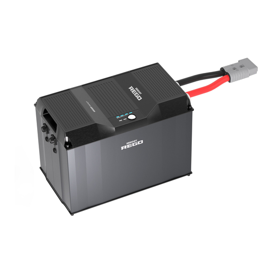
Product Overview DC-DC Battery Charger BVS BTS input output Part Part Mounting Holes Negative Output Terminal Fault Status Indicator Positive Output Terminal Battery Status Indicator CAN Communication Ports Battery Type Setting Knob IGN Signal Wire Port Positive Input Terminal BVS (Battery Voltage Sensor) Port Negative Input Terminal BTS (Battery Temperature Sensor) Port z Please inspect the battery charger for any visible damage including cracks, dents,... -
Page 6: Installation
Installation Recommended Components Battery Scenario A: REGO Battery Kit Renogy REGO Lithium Battery Renogy REGO System Combiner Box Battery Adapter Cable (output) ( Anderson Battery Adapter Cable (input) ( Anderson PP75 to Anderson 120 Adapter Cable ) PP75 to Ring Terminal Adapter Cable ) - Page 7 Installation *Optional Accessories *Battery Voltage Sensor *Battery Fuse (80A) *Fuse Cable (Model: RVSCC) Required Tools Wrench (10mm) Wrench (14mm) Measuring Tape Insulation Tape...
- Page 8 Installation Mounting Location z Risk of explosion! Never install the battery charger in a sealed enclosure with flooded batteries! Do not install in a confined area where battery gases can accumulate. z Place the battery charger on a vertical surface protected from direct sunlight, high temperatures, and water.
- Page 9 Installation Battery Charger Wiring z Please refer to the user manual of the battery charger at renogy.com for the recommended wire gauge and length. z Please make sure that the connections of the Anderson connectors are tight and secure. REGO Battery Kit...
- Page 10 160A NH fuse in the top NH fuse disconnect switch. z If the Anderson PP75 to Ring Terminal Adapter Cable is used to connect with the System Combiner Box, please refer to the user manual of REGO 12V 60A DC-DC Battery Charger at renogy.com for more detailed instructions.
- Page 11 Once the battery wiring is completed correctly and the battery is turned on, the battery charger's Battery indicator lights up green. If the Battery indicator does not light up, please refer to the user manual of the battery charger at renogy.com for troubleshooting instructions. STEP-3.5...
- Page 12 DC generator. If you want to wire directly to the DC generator, please refer to the user manual of REGO 12V 60A DC-DC Battery Charger at renogy.com for more detailed instructions. z Please check the vehicle's manual to identify the generator type before connecting. If you cannot identify the generator type, please refer to the user manual of battery charger at renogy.com for more detailed instructions.
- Page 13 After waiting for 15S, the Battery indicator flashes green and the battery charger starts to work. If the Battery indicator does not light up, please refer to the user manual of the battery charger at renogy.com for troubleshooting instructions. STEP-4.5...
- Page 14 -20°C to 60°C or -4°F to 140°F) can charge the battery normally. z Do not use the temperature sensor on a LiFePO4 (LFP) battery which comes with a battery management system (BMS). z Please refer to the user manual of battery charger at renogy.com for more matters needing attention. BVS BTS BVS BTS STEP-6.1...
- Page 15 fix it to prevent it from falling off. Insert the voltage sensor terminal block to the BVS port. BVS BTS BVS BTS STEP-7.1 Connect the voltage sensor REGO Battery ring terminal to the positive/ negative pole of the battery system. Normal Battery with +/- Bolts STEP-7.2...
-
Page 16: Led Indicators
Battery indicator lights up blue and remains solid. Fault Status Indicator STEP-8.4 STEP-8.5 Under normal conditions, the If the Fault indicator lights up, please refer to the user manual Fault indicator will not light of the battery charger at renogy.com for troubleshooting instructions. -
Page 17: Communication
Communication The communication connection is optional. The communication between REGO products allows safe operation, smart control, and close monitoring. Depending on the installation condition, the communication connection needs to be established with backbone or daisy chain topology. Backbone Topology If an RV-C bus is pre-installed in the RV, please follow the backbone topology for the communication connection. - Page 18 Communication STEP-9.1 STEP-9.2 Insert the bare wires of the Drop Cable (sold Squeeze the crimp area of the Drop Plug with separately) all the way into the wire ports of a pair of split joint pliers. the Drop Plug (not included) following the Drop Plug pinout.
- Page 19 LP16 Terminator Plug (7-Pin) STEP-9.5 STEP-9.6 Connect REGO devices in Plug the Termionator Plug (sold separately) into the free CAN series through either of the Communication Ports on the first and last REGO devices. CAN Communication Ports with the Communication Cables (sold separately).
-
Page 20: Operation & Maintenance
Ensure there is no any corrosion, insulation damage, or discoloration marks of overheating or burning. z Risk of electric shock! Make sure that all power is turned off before touching the terminals on the battery charger. z Please refer to the user manual of the battery charger at renogy.com for more details. - Page 21 Renogy Power PLUS Renogy Power Plus allows you to stay in the loop with upcoming solar energy innovations, share your experiences with your solar energy journey, and connect with like-minded people who are changing the world in the Renogy Power Plus community.
- Page 22 RENOGY.COM Visit renogy.com to find the User Manual or get more support via "Contact Us". Renogy reserves the right to change the contents of this manual without notice. Your voice matters! Scan the QR code to submit your feedback on the product.
Need help?
Do you have a question about the REGO and is the answer not in the manual?
Questions and answers