Table of Contents
Advertisement
Quick Links
Advertisement
Table of Contents

Related Manuals for RuggedCom RuggedSwitch RS969


Summary of Contents for RuggedCom RuggedSwitch RS969
-
Page 1: Installation Guide
RuggedSwitch RuggedSwitch™ ™ ™ ™ RS969 RuggedSwitch RuggedSwitch RS969 RS969 RS969 Installation Guide www.ruggedcom.com RuggedCom Inc. I 30 Whitmore Road, Woodbridge, Ontario, Canada L4L 7Z4 Tel: 905-856-5288 I Fax: 905-856-1995 I Toll Free: 1-888-264-0006... -
Page 2: Federal Communications Commission Radio Frequency Interference Statement
Operation of this equipment in a residential area is likely to cause harmful interference in which case the user will be required to correct the interference on his own expense. Warning: Changes or modifications not expressly approved by RuggedCom Inc. could void the user’s authority to operate the equipment. Caution: This product contains a laser system and is classified as a “CLASS 1 LASER PRODUCT”. -
Page 3: Table Of Contents
Mechanical Specifications .................... 24 3.10 Agency Approvals......................26 Accessories..........................27 4.1 POWER (1/unit) ........................27 4.2 CONSOLE (1/unit) ....................... 27 4.3 FAILSAFE (1/unit)........................ 28 4.4 ETHERNET (8/unit) ......................29 4.5 LC FIBER OPTIC (2/unit)..................... 30 Warranty..........................31 © 2008 RuggedCom Inc. All rights reserved Rev104... -
Page 4: Product Overview
• Loss of link management on fiber ports • Conformal coated circuit boards (optional) • Web-based, Telnet, CLI management interfaces • SNMP v2 and RMON • Rich set of diagnostics with logging and alarms © 2008 RuggedCom Inc. All rights reserved Rev104... -
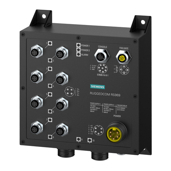
Page 5: Rs969 Family Ports/Connectors Description
1.1 RS969 Family Ports/Connectors Description Figure 1.1.1 RS969–M12 with Mini-Change Power Connector © 2008 RuggedCom Inc. All rights reserved Rev104... - Page 6 LINK LED (Yellow) Solid Link Established Blinking Tx/Rx Activity Power 1 LED Solid Power Supply 1 On Power 2 LED Solid Power Supply 2 On Alarm LED (Red) Solid Alarm condition exists © 2008 RuggedCom Inc. All rights reserved Rev104...
-
Page 7: Installation
An optional DIN rail mounting bracket is available for the RS969. Figure 2.1.1 details mounting instructions for the standard 1” DIN Rail. Optional DIN Rail Mounting Rail Bracket Release Latch Release Direction Figure 2.1.1 RS969 Family DIN Rail Mounting © 2008 RuggedCom Inc. All rights reserved Rev104... -
Page 8: Ingress Protection Ip67
Protected against the effects of permanent submersion in water The RuggedCom M969 Industrial Ethernet Switch is manufactured and tested to IP67 standards. With an IP67 rating a product will be "dust tight" and remain completely sealed when immersed in water to a depth of 1 meter for 1 hour. (IEC 60529) These caps completely seals off unused ports on the IP67 Industrial Ethernet Switch. -
Page 9: Power Supply Wiring And Grounding
S u r g e G r o u n d C h a s s is G ro u n d Figure 2.2.1.2 RS969 Family Surge Ground / Chassis Ground Connection © 2008 RuggedCom Inc. All rights reserved Rev104... - Page 10 PS2 Neutral / - the power source is DC or to the (Neutral) terminal if the power source is AC. Table 1: RS969 Power terminal block connection description for M23 A-code male connector © 2008 RuggedCom Inc. All rights reserved Rev104...
- Page 11 3. All line-to-ground transient energy is shunted to the Surge Ground terminal. In cases where users require the inputs to be isolated from ground, remove the ground braid between Surge and Chassis Ground. All line-to-ground transient protection circuitry will be disabled. © 2008 RuggedCom Inc. All rights reserved Rev104...
-
Page 12: Single Ac Power Supply Wiring Examples
2. Equipment must be installed according to the applicable country wiring codes. 3. When equipped with two HI voltage power supplies, independent AC sources can be used to power the product for greater redundancy. © 2008 RuggedCom Inc. All rights reserved Rev104... -
Page 13: Single Dc Power Supply Wiring Examples
2. A circuit breaker is not required for 12, 24 or 48 VDC rated power supplies. 3. For dual DC power supplies, Separate circuit breakers must be installed and separately identified. 4. Equipment must be installed according to the applicable country wiring codes. © 2008 RuggedCom Inc. All rights reserved Rev104... -
Page 14: Dual Power Supplies - Dc And Ac Inputs
2.3.4 Dual Power Supplies – DC and AC Inputs © 2008 RuggedCom Inc. All rights reserved Rev104... - Page 15 2. A circuit breaker is not required for 12, 24 or 48 VDC rated power supplies. 3. Separate circuit breakers must be installed and separately identified. 4. Equipment must be installed according to the applicable country wiring codes. © 2008 RuggedCom Inc. All rights reserved Rev104...
-
Page 16: Dielectric Strength (Hipot) Testing
Figure 4 shows the proper dielectric strength test connections and should be followed to avoid damage to the device. Surge Ground Chassis Ground Figure 4: Dielectric Strength (HIPOT) Testing © 2008 RuggedCom Inc. All rights reserved Rev104... -
Page 17: Failsafe Alarm Relay Wiring And Specifications
Normal Contact state without power being applied to unit 1. Normally closed 2. Common 3. Normally open Figure 5: Failsafe Alarm Relay Wiring © 2008 RuggedCom Inc. All rights reserved Rev104... -
Page 18: Console Port Wiring
7. Console connection settings are: 57600 baud, no parity bits, 8 data bits, and 1 stop bit. Figure 6: Console port Figure 7: RS969 Console cable For user reference, the console cable pin-out is show in Table 5. RuggedCom RS232 over M12 pin-out specification Signal Name (PC is DTE) DB9- Female M12- Male RxD –... -
Page 19: Fast Ethernet Ports - Signal Description
Case Shield (Chassis Ground) Figure 2.6.1 RJ45 Port and M12 Port Pins NOTE: RuggedCom does not recommend the use of CAT-5 cabling of any length for critical real- time substation automation applications. However, transient suppression circuitry is present on all copper ports to protect against damage from electrical transients and to ensure IEC 61850-3 and IEEE 1613 Class 1 conformance. -
Page 20: Technical Specifications
For continued protection against risk of fire, replace only with same type and rating of fuse. 3.3 Failsafe Relay Specifications Parameter Value Max Switching Voltage 30VAC, 80VDC Rated Switching Current 0.3A @ 30VAC 1A @ 30VDC, 0.3A @ 80VDC NOTES: Resistive Load. For Class-2 circuits only. © 2008 RuggedCom Inc. All rights reserved Rev104... -
Page 21: Twisted Pair Data Port Specifications
RJ45 or M12 3.5 Fiber Optical Port Specifications For maximum flexibility RuggedCom Inc. offers a number of different transceiver choices for Gigabit fiber optical communications. The following table details fiber optic specifications based on the order code / transceiver selected at time of ordering. -
Page 22: Iec 61850-3 Type Tests
2kV AC (Fail-Safe Relay output) IEC 60255-5 Dielectric Strength D.C. Power ports 2kV AC A.C. Power ports 2kV AC Signal ports 5kV (Fail-Safe Relay output) IEC 60255-5 H.V. Impulse D.C. Power ports A.C. Power ports © 2008 RuggedCom Inc. All rights reserved Rev104... -
Page 23: Ieee 1613 Type Tests
100l/m @ 2.5m as per 14.2.6 IEC 60529 (IPx7) Ingress Protection Water Submersion 30 min @ 1m as per 14.2.7 IEC 60529 (IP6x) Ingress Protection Dust Talcum 2kg/m3 for 8h as per 13.4 Cat. 1&2 © 2008 RuggedCom Inc. All rights reserved Rev104... -
Page 24: Mechanical Specifications
3.9 Mechanical Specifications © 2008 RuggedCom Inc. All rights reserved Rev104... - Page 25 Parameter Value Comments Dimensions 7,75 x 7,0 x 4,28 inches (Length x Width x Depth) (196,85) x (177,8) x (108,7) mm Enclosure Die-cast Aluminum © 2008 RuggedCom Inc. All rights reserved Rev104...
-
Page 26: Agency Approvals
Approved EN 60950, EN 61000-6-2 Approved FCC Part 15, Class A Approved CISPR EN55022, Class A Approved FDA/CDRH 21 CFR Chapter 1, Subchapter J Approved IEC/EN EN60825-1:1994 + A11:1996 + A2:2001 Approved © 2008 RuggedCom Inc. All rights reserved Rev104... -
Page 27: Accessories
M12 Console Port Mating Cable Description: M12 8pin A-code male to DB9 female; unshielded, PUR jacket cable, 30V/4A, 3m RuggedCom P/N 43-10-0023 Cable specs: M12 8pin A-code male to free end, 3m © 2008 RuggedCom Inc. All rights reserved Rev104... -
Page 28: Failsafe (1/Unit)
M12 FailSafe Port Mating Cable Description: M12 4pole A-coded; unshielded, PUR Jacket cable, 3m RuggedCom P/N 43-10-0024 M12 FailSafe Port Mating Connector Description: M12-straight plug, 4 pole, A-coded, IP67 rated RuggedCom P/N 30-50-0017 © 2008 RuggedCom Inc. All rights reserved Rev104... -
Page 29: Ethernet (8/Unit)
Description: M12-straight plug, 4 pole, D-coded, IP67 rated RuggedCom P/N 30-50-0015 IP67 RJ45 Ethernet Port Mating Cable Description: IP67 RJ45 plug to RJ45; Category 5e shielded patch cable, 3.1m RuggedCom P/N 43-10-0029 © 2008 RuggedCom Inc. All rights reserved Rev104... -
Page 30: Lc Fiber Optic (2/Unit)
Description: IP67 Singlemode LC plug RuggedCom P/N 30-50-0023 LC Port Mating Connector Description: Multimode IP67 LC plug to LC connector, 3m RuggedCom P/N 43-10-0044 Description: Singlemode IP67 LC plug to LC connector, 3m RuggedCom P/N 43-10-0043 © 2008 RuggedCom Inc. All rights reserved Rev104... -
Page 31: Warranty
5 Warranty Five (5) years from date of purchase, return to factory. For warranty details, visit www.ruggedcom.com or contact your customer service representative. Should this product require warranty or service contact the factory at: RuggedCom Inc. 30 Whitmore Road, Woodbridge, Ontario...
Need help?
Do you have a question about the RuggedSwitch RS969 and is the answer not in the manual?
Questions and answers