
Related Manuals for MasterCraft Maximum Hawkeye Laser 055-6746-0


Summary of Contents for MasterCraft Maximum Hawkeye Laser 055-6746-0
- Page 1 Dual-beveling Compound Mitre Saw 055-6746-0 Owner’s Manual Toll-Free Helpline 1-800-689-9928...
-
Page 2: Table Of Contents
Table of contents SECTION PAGE Specifications..................Symbols....................III. General safety rules................Specific safety rules for the mitre saw..........Electrical information................Know your mitre saw................VII. Glossary of terms................VIII. Assembly and adjustments..............Operations ..................Maintenance..................Troubleshooting guide................. XII. Warranty....................XIII. -
Page 3: Symbols
Symbols WARNING ICONS Your power tool and its Owner’s Manual may contain “WARNING ICONS” (a symbol intended to alert you to and/or instruct you how to avoid a potentially hazardous situation). Understanding and heeding these symbols will help you operate your tool better and more safely. -
Page 4: General Safety Rules
III. General safety rules Safety is a combination of common sense, staying alert, and knowing how the mitre saw works. WARNING: To avoid mistakes that could cause serious injury, read this owner’s manual carefully before plugging in the mitre saw. READ and become familiar with this Owner’s Manual. - Page 5 III. General safety rules (continued) 13. DO NOT LEAVE THE POWER SWITCH IN THE ON POSITION WHILE THE TOOL IS UNATTENDED. Turn the power switch to the OFF position. DO NOT leave the tool until it has come to a complete stop. 14.
-
Page 6: Specific Safety Rules For The Mitre Saw
IV. Specific safety rules for the mitre saw 1. USE ONLY CROSSCUTTING SAW BLADES. When using carbide-tipped blades, make sure they have a negative hook angle. Do not use blades with deep gullets, because they can deflect and contact the guard. The use of thin-kerf blades is not recommended. 2. - Page 7 IV. Specific safety rules for the mitre saw (continued) 19. MAKE SURE the blade is not contacting the workpiece before the switch is turned ON. 20. NEVER unplug the saw with the switch in the ON position. IMPORTANT: After completing the cut, release the power switch and wait for the blade to stop before returning the saw to the raised position.
-
Page 8: Electrical Information
V. Electrical information POWER SUPPLY AND MOTOR SPECIFICATIONS The AC motor used in this saw is a universal, non-reversible type. See “MOTOR” in the “PRODUCT SPECIFICATIONS” section on page 2. WARNING: To avoid electrical hazards, fire hazards, or damage to the tool, use proper circuit protection. - Page 9 V. Electrical information (continued) Make sure your extension cord is properly wired and in good condition. Always replace a damaged extension cord or have it repaired by a qualified technician before using it. Protect your extension cords from sharp objects, excessive heat and damp or wet areas. Use a sep arate electrical circuit for your tool.
-
Page 10: Know Your Mitre Saw
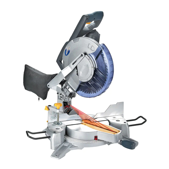
VI. Know your compound mitre saw Safety lock-off switch Switch Handle Cover Plate Upper Blade Guard Lower Blade Guard Motor Fence Bevel Lock Handle Table Sliding Fence Table Insert Base Mitre Handle Mitre Scale Left Extension Bracket Mounting Hole ON/OFF Trigger Switch Carry Handle Arbor Lock Belt Cover... -
Page 11: Glossary Of Terms
VII. Glossary of terms AMPERAGE (AMPS) – A measure of the flow of electric current. Higher ratings generally means the tool is suited for heavier use. ARBOR LOCK – Allows the user to keep the blade from rotating while tightening or loosening the arbor bolt during blade replacement or removal. - Page 12 VII. Glossary of terms (continued) POSITIVE STOP LOCKING LEVER – Locks the mitre saw at a preset positive stop for the desired mitre angle. SWITCH HANDLE – The switch handle contains the trigger switch and safety lock-off button. The blade is lowered into the workpiece by pushing down on the handle. The saw will return to its upright position when the handle is released.
-
Page 13: Assembly And Adjustments
VIII. Assembly and adjustments UNPACKING 1. Carefully remove the mitre saw from the carton. 2. Separate the parts. 3. Lay out all of the parts, and check them against the parts listed below. Examine all of the parts carefully. WARNING: If any part is missing or damaged, do not plug the mitre saw in until the missing or damaged part has been repaired or replaced. - Page 14 VIII. Assembly and adjustments (continued) Estimated Assembly Time: 5-10 minutes ASSEMBLY INSTRUCTIONS WARNING: To avoid injury, do not connect this mitre saw to the power source until it is completely assembled and adjusted and you have read and understood this owner’s manual.
- Page 15 VIII. Assembly and adjustments (continued) INSTALLING THE DUST BAG (FIG. 3) Fig. 3 1. Squeeze the metal collar wings (1) of the dust bag (2). 2. Place the dust bag neck opening around the exhaust port (3), and release the metal collar wings.
- Page 16 VIII. Assembly and adjustments (continued) INSTALLING THE SAFETY HOLD-DOWN Fig. 6 CLAMP (FIG. 6) 1. Place the hold-down clamp assembly (1) in one of the mounting holes (2) as shown. WARNING: ● Only use a 12’’ (30.5 cm) diameter blade. ●...
- Page 17 VIII. Assembly and adjustments (continued) REMOVING AND INSTALLING THE Fig. 8 BLADE Removing Blade (Fig. 8, 9, 10, 11) 1. Unplug the saw from the outlet. 2. Allow the blade assembly to rise to the uppermost position. Raise the lower blade guard (1) to the upper position.
- Page 18 VIII. Assembly and adjustments (continued) Installing Blade (Fig. 8, 9, 10, 11) Unplug the mitre saw before changing/installing the blade. 1. Install a 12’’ (30.5 cm) blade with a 5/8’’ (15.9 mm) arbor (or a 1” (2.5 cm) arbor with a 5/8”...
- Page 19 VIII. Assembly and adjustments (continued) MOUNTING THE MITRE SAW Fig. 12 (FIG. 12, 13) Mounting instructions 1. Mitre saw base 2. Hex head bolt 1. For stationary use, place the saw in the 3. Rubber washer desired location, directly on a workbench 4.
- Page 20 VIII. Assembly and adjustments (continued) WARNING: To avoid injury from an accidental start, make sure the switch is in the off position and the plug is not connected to the power source. BEVEL STOP ADJUSTMENT (FIG. 14, 15, 16) 90°...
- Page 21 VIII. Assembly and adjustments (continued) WARNING: To avoid injury from an accidental start, make sure the switch is in the off position and the plug is not connected to the power source. 45° Right Bevel Positive Stop Fig. 17 Adjustment (Fig.
- Page 22 VIII. Assembly and adjustments (continued) 33.9° Right Bevel Adjustment (Fig. 19) Fig. 19 1. Set the mitre angle to 0°. Fully extend both sliding fences. 2. Loosen the bevel lock handle (1). 3. Set the stop block (2) at 33.9° position by turning the lever (3) clockwise.
- Page 23 VIII. Assembly and adjustments (continued) SQUARING THE FENCE (FIG. 21) Fig. 21 1. Loosen the four fence locking bolts (1). 2. Lower the cutting arm and lock in position. 3. Using a square (2), lay the heel of the square against the blade and the ruler against the fence (3) as shown.
- Page 24 VIII. Assembly and adjustments (continued) POSITIVE STOP MITRE ANGLE Fig. 24 ADJUSTMENT (FIG. 24) 1. Unlock the mitre table by lifting up on the mitre quick-cam locking lever (1). 2. While raising the positive stop locking lever (2) up, grasp the mitre handle and rotate the mitre table left or right to the desired angle.
-
Page 25: Operations
IX. Operation SAFETY INSTRUCTIONS FOR BASIC SAW OPERATION BEFORE USING THE MITRE SAW WARNING: ● To avoid mistakes that could cause serious, permanent injury, do not plug the tool in until the following steps are completed: ● Completely assemble and adjust the saw following the instructions (assembly and adjustments). - Page 26 IX. Operation (continued) ● Keep all guards in place, in working order and properly adjusted. If any part of this mitre saw is missing, bent, damaged or broken in any way, or if any electrical parts do not work, turn the saw off and unplug it. Replace damaged, missing, or defective parts before using the saw again.
- Page 27 IX. Operation (continued) CAUTION: This machine is NOT designed for cutting masonry, masonry products & ferrous metals (steel, iron, and iron-based metals). Use this mitre saw to cut only wood & wood-like products. Other material may shatter, bind the blade, or create other dangers.
- Page 28 IX. Operation (continued) USE EXTRA CAUTION WITH LARGE OR ODD-SHAPED WORKPIECES ● Use extra supports (tables, sawhorses, blocks, etc.) for workpieces that are large enough to tip. ● Never use another person as a substitute for a table extension, or as an additional support for a workpiece that is longer or wider than the basic mitre saw table, or to help feed, support, or pull the workpiece.
- Page 29 IX. Operation (continued) BODY AND HAND POSITION (FIG. 25) WARNING! Never place hands near the cutting area. Proper positioning of your body and hands when operating the mitre saw will make cutting easier and safer. Keep children away. Keep all visitors at a safe distance from the mitre saw.
- Page 30 IX. Operation (continued) THE LASER GUIDE (FIG. 26) Fig. 26 1. To turn laser on, turn switch (1) to “I” position. 2. To turn laser off, turn switch to “O” position. THE LASER BEAM WARNING: ● FOR YOUR OWN SAFETY, NEVER CONNECT THE PLUG TO A POWER SOURCE OUTLET UNTIL YOU HAVE READ AND UNDERSTOOD THE SAFETY AND OPERATIONAL INSTRUCTIONS.
- Page 31 IX. Operation (continued) AVOID DIRECT EYE CONTACT WARNING: ● Laser radiates when laser guide is turned on. Avoid direct eye contact. Always unplug the mitre saw from power source before making any adjustments. ● LASER RADIATION. Do not stare into the beam or view it directly using optical instruments. Maximum output: <...
- Page 32 IX. Operation (continued) BASIC SAW OPERATIONS WARNING: ● For your convenience, your saw has a blade brake. The brake is not a safety device. Never rely on it to replace the proper use of the guard on your saw. ●...
- Page 33 IX. Operation (continued) SLIDING FENCE (FIG. 29) Fig. 29 1. Unlock the fence cam locking knob (1) by pushing it toward the rear of the machine. 2. Extend the fence (2) by sliding it out to match the degree of the bevel cut. Lock the fence cam locking lever by pushing it IN toward the fence.
- Page 34 IX. Operation (continued) 33.9° CROWN MOULDING (FIG. 32) Fig. 32 NOTE: When cutting crown moulding the bevel angle should be set 33.9° right or left. 1. Loosen the bevel lock handle (1), 2. Rotate the bevel stop block (2) and set bevel angle at the 33.9°...
- Page 35 IX. Operation (continued) WORKPIECE SUPPORT AND Fig. 35 REPETITIVE CUTTING USING THE STOP PLATE (FIG. 35) Long pieces need extension table support. 1. Loosen the knob (1), and then slide the extension wing to desired position and tighten the knob. 2.
- Page 36 IX. Operation (continued) CUTTING BASE MOULDING (FIG. 37) Fig. 37 Base mouldings and trims can be cut on a compound mitre saw. The method depends on the type of moulding, its characteristics and applications. 1. Use vise clamps, hold-down or C-clamps whenever possible.
- Page 37 IX. Operation (continued) Bevel/Mitre Settings NOTE: The chart below references a compound cut for crown moulding ONLY WHEN THE ANGLE BETWEEN THE WALLS EQUALS EXACTLY 90°. KEY BEVEL SETTING MITRE SETTING TYPE OF CUT Inside corner - Left side 1. Position top of moulding against fence. 33.9°...
- Page 38 IX. Operation (continued) CROWN MOULDING CHART Compound Mitre Saw Mitre and Bevel Angle Settings Wall to Crown Moulding Angle ° ° 52/38 Crown Moulding 45/45 Crown Moulding Angle Between Walls Mitre Setting Bevel Setting Mitre Setting Bevel Setting 42.39 41.08 46.69 36.13 42.39...
- Page 39 IX. Operation (continued) ° ° 52/38 Crown Moulding 45/45 Crown Moulding Angle Between Walls Mitre Setting Bevel Setting Mitre Setting Bevel Setting 18.13 21.71 20.61 19.39 17.77 21.34 20.21 19.06 17.42 20.96 19.81 18.72 17.06 20.59 19.42 18.39 16.71 20.21 19.03 18.06 16.37...
-
Page 40: Maintenance
X. Maintenance MAINTENANCE WARNING: ● NEVER PUT LUBRICANTS ON THE BLADE WHILE IT IS SPINNING. ● TO AVOID FIRE OR TOXIC REACTION, NEVER USE GASOLINE, NAPHTHA ACETONE, LACQUER THINNER OR SIMILAR HIGHLY VOLATILE SOLVENTS TO CLEAN THE MITRE SAW. ●... - Page 41 X. Maintenance (continued) WARNING: ● When cleaning the lower guard, unplug the saw from the power source to avoid unexpected startup. ● Do not use solvents on the guard. They could make the plastic “cloudy” and brittle. ● Periodically, sawdust will accumulate under the work table and base. This could cause difficulty in the movement of the worktable when setting up a mitre cut.
-
Page 42: Troubleshooting Guide
XI. Troubleshooting guide WARNING: In order to avoid injury from an accidental start-up, always turn the switch to the OFF position and unplug the mitre saw before moving the mitre saw or the blade, replacing the blade, or making adjustments to the mitre saw or the blade. TROUBLESHOOTING GUIDE –... -
Page 43: Warranty
The provisions contained in this warranty are not intended to limit, modify, take away from, disclaim or exclude any statutory warranties set forth in any applicable provincial or federal legislation. Imported by Mastercraft Canada Toronto, Canada M4S 2B8... -
Page 44: Replacement Parts
COMPOUND MITRE SAW WITH LASER LINE ® ® When servicing the Mastercraft Maximum Compound Mitre Saw, use only Mastercraft ® ® ® replacement parts. The use of any other parts may cause damage to the product. All servicing should be performed by a qualified service technician. - Page 45 XIII. Replacement parts MASTERCRAFT MAXIMUM COMPOUND MITRE SAW WITH LASER LINE ® ®...
- Page 46 Notes...
- Page 47 Notes...
- Page 48 Notes Imported by Mastercraft Canada Toronto, Canada M4S 2B8...
Need help?
Do you have a question about the Maximum Hawkeye Laser 055-6746-0 and is the answer not in the manual?
Questions and answers
How to change the blade