Advertisement
OPERATING MANUAL
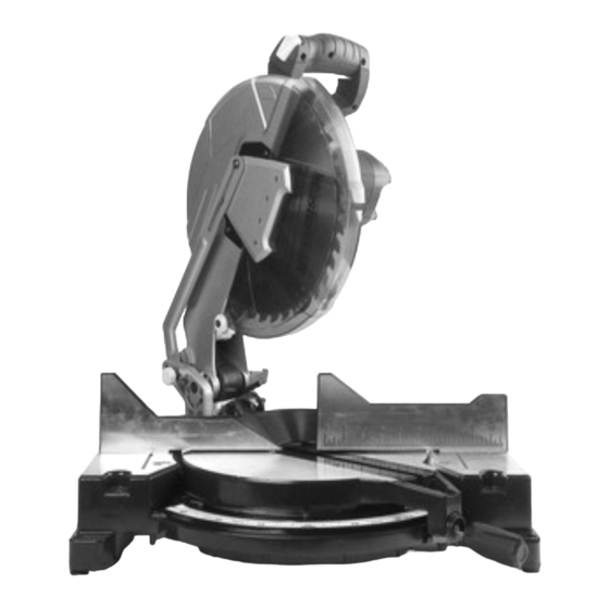
12" COMPOUND MITRE SAW
WITH LASER
55-6898-8
Parts missing or damaged? Questions? Toll-Free Help Line – 1-800-689-9928
IMPORTANT:
Read through this operating manual carefully before using this tool. Pay close
attention to all Safety Instructions, Warnings, and Caution sections. Use this tool
properly and only for its intended use.
Safety symbols in this manual are used to call attention to possible dangers.
The safety symbols and their explanations require the operator's full understanding.
The safety warnings do not, by themselves, eliminate any danger, nor are they a
substitute for proper accident-prevention measures.
This Safety Alert Symbol indicates caution, warning, or danger. Failure to obey
a safety warning can result in serious injury to the operator or to others. To reduce
the risk of injury, fire, or electric shock, always follow the safety precautions.
1
Advertisement
Table of Contents

Related Manuals for MasterCraft 55-6898-8


Summary of Contents for MasterCraft 55-6898-8
- Page 1 OPERATING MANUAL 12” COMPOUND MITRE SAW WITH LASER 55-6898-8 Parts missing or damaged? Questions? Toll-Free Help Line – 1-800-689-9928 IMPORTANT: Read through this operating manual carefully before using this tool. Pay close attention to all Safety Instructions, Warnings, and Caution sections. Use this tool properly and only for its intended use.
-
Page 2: Table Of Contents
TABLE OF CONTENTS Specifications…………………………………………..Page 2 Rules for Safe Operation……………………… ….. Page 3-7 Glossary of Woodworking Terms……………………Page 8 Description…………………………………….....Page 9 Assembly……………………..……..... Page 10-11 Adjustments............. Page 12 Operation....………………….....Page 13-20 Maintenance............Page 20 Troubleshooting............Page 21 Repair Parts.............Page 22 Exploded View & Part List........Page 23-24 Warranty………………………………………………..Page 25 SPECIFICATIONS Motor:... -
Page 3: Rules For Safe Operation
RULES FOR SAFE OPERATION KNOW THE TOOL To operate this tool safely, carefully read this operating manual and all the labels affixed to the Compound Mitre Saw before using it, and follow all instructions contained therein. Retain this manual for future reference. MPORTANT This tool should only be serviced by a qualified service technician. - Page 4 GENERAL SAFETY PRECAUTIONS Read and become familiar with the entire Operating Manual. Learn the tool’s application, limitations, and possible hazards. Keep the guard in place and in working order. Remove all adjusting tools before turning tools on. Form the habit of checking to see that keys and adjusting wrenches are removed from the tool before turning the tool ON.
- Page 5 WARNING: The operation of any tool can result in foreign objects being propelled into the eyes, which could result in severe eye damage. When operating a power tool, always wear safety goggles or safety glasses with side shields, or a full- face shield, if necessary.
- Page 6 GUIDELINES FOR EXTENSION CORDS Use a proper extension cord. Make sure that extension cords are in good condition. When using an extension cord, be sure to use a cord heavy enough to carry the drawn current needed by the Compound Mitre Saw. An undersized cord will cause a drop in line voltage, resulting in loss of power and overheating.
- Page 7 Allow the motor to come up to full speed before starting a cut. Keep the motor’s air slots clean and free of chips or dust. Always make sure that all adjusting knobs are tightened before cutting, even if the table is positioned in one of the positive stops. Be sure that both the blade and the flange are clean and the arbour bolt is tightened securely.
-
Page 8: Glossary Of Woodworking Terms
GLOSSARY OF TERMS FOR WOODWORKING • Arbour: The revolving shaft on which a blade or cutting tool is mounted. • Arbour Lock: Allows the user to stop the blade from rotating while tightening or loosening the arbour screw during blade replacement or removal. •... -
Page 9: Description
DESCRIPTION KNOW THE COMPOUND MITRE SAW (See Fig. 1) Before attempting to use this Compound Mitre Saw, become familiar with all its operating features and safety requirements. Fig.1 ON/OFF trigger switch Horizontal, rubberized D-handle Safety lock-off button Upper blade guard Blade-screw guard Dust-extraction port Saw blade... -
Page 11: Assembly
ASSEMBLY Fig. 2 Installation of dust bag (see Fig. 2) Dust bag Squeeze the metal collar wings on the dust bag, and Dust place the bag’s neck opening around the dust- extraction extraction port. Release the metal collar wings. port Installation of adapter for shop vacuum Remove the dust extraction port for the dust bag by removing the two screws that hold it in place. - Page 12 Installing the blade IMPORTANT: Do not use thin-kerf blades. Thin-kerf blades can deflect and contact the guard, which can cause injury to the operator. 1. Unplug the saw 2. Ensure that the inner flange is properly installed 3. Match the arrow on the blade with the arrow on the upper blade guard. Make sure that the blade teeth are pointing downward.
-
Page 13: Adjustments
ADJUSTMENT WARNING: To avoid possible injury, disconnect the tool’s plug from the power source before performing any assembly, adjustment, or repair. IMPORTANT: Do not use thin-kerf blades. Thin-kerf blades can deflect and contact the guard, which can cause injury to the operator. Mitre adjustment Lock the saw head in the down position, and loosen the mitre-lock knob. -
Page 14: Operation
OPERATION WARNING: To reduce the risk of injury, wear safety goggles or glasses with side shields. WARNING: Before each use, check that the blade is free from cracks, loose teeth, missing teeth, or any other damage. Do not use if damage is noticed or suspected. - Page 15 Support the work piece WARNING: Never use the help of another person as a substitute for a table extension, as support for a work piece that is longer or wider than the basic mitre table. Never have another person help feed, support, or pull the work piece instead of using table extensions.
- Page 16 Pay attention to body and hand positions. Proper positioning of the body and hands when operating the Mitre Saw will make cutting easier and safer. Never place hands near the cutting area. Hold the work piece firmly against the fence. Keep hands in position until the ON/OFF trigger switch has been released and the blade has completely stopped.
- Page 17 5. Quickly locate 0°, 15°, 22.5°, 31.6° and 45°, left or right, by the stops or clicks at these angle settings. 6. Once the mitre angle is set, tighten the mitre-lock lever by tightening the mitre- lock knob. 7. Pull out the locking pin to release the saw arm. 8.
- Page 18 BEVEL CUTTING (Fig. 13) A bevel cut is a cut made across the grain of the work piece with the blade at an angle to the work piece. A straight bevel cut is made with the mitre table set in the 0° position and the saw arm set at a bevel angle between 0°...
- Page 19 saw arm to make sure that no problems will occur when the cut is made. 11. Hold the saw handle and use the index finger to turn on the laser switch by pushing it forward. 12. To turn on the saw, push the safety-lock button in with the thumb while squeezing the On/Off trigger switch located under the handle (Fig.1-1 and Fig.1-3).
- Page 20 WARNING: To avoid serious personal injury, always securely tighten the mitre-lock lever before making a cut. Failure to do so could result in movement of the control arm or mitre table while making a cut. 7. To set the bevel angle, loosen the bevel-lock knob (Fig. 1-22) by turning the knob counter clockwise.
-
Page 21: Maintenance
CUTTING WARPED MATERIAL (Fig. 15 and 16) WARNING: To avoid kickback and to avoid serious personal injury never position the concave side of bowed or warped material against the fence. When cutting warped material, be certain that the material to be cut is positioned on the mitre table with the convex side against the fence, as shown (Fig. -
Page 22: Troubleshooting
TROUBLESHOOTING PROBLEM PROBABLE CAUSE SUGGESTED CORRECTIVE ACTION Brake does not stop blade within Electric hand brake has failed Take saw for servicing 6 seconds Motor brake overheated from Use a recommended blade use of defective or wrong size blade or rapid ON/OFF cycling Arbour bolt is loose Retighten Motor does not start... -
Page 23: Repair Parts
Repair Parts INCLUDES: • 1 pc of 40T carbide tip blades • 1 pc of hold clamp • 1 pc of dust collection bag • 1 pair of extension rails • 1 pc wrench • 1 pc vacuum adapter... - Page 24 Exploded View...
- Page 25 Parts List Name Qty. Name Qty. Name Qty. Screw Blade flange Screw Motor cover Blade Angle orientation Screw Blade flange Spring washer Brush Blade bolt Screw Brush spring Rivet Turntable Brush hold Moving guard Mitre pointer Screw Special screw Clamp nut Spring washer Cast centre Clamp plate...
-
Page 26: Warranty
MASTERCRAFT LIMITED WARRANTY This Mastercraft® product is guaranteed three (3) years from the date of original retail purchase] against defects in materials and workmanship, Subject to the conditions and limitations described below, this product, if returned to us with proof of purchase within the stated warranty period and if covered under this warranty, will be repaired or replaced (with the same model, or one of equal value or specification), at our option.
Need help?
Do you have a question about the 55-6898-8 and is the answer not in the manual?
Questions and answers