Table of Contents
Advertisement
Quick Links
Inclined-Orbit tracking
Allows single axis tracking for modest-sized
antennas with a motorized declination axis
!
Three Track Modes
Step Track, Memory & Search modes
supported
!
Polarization Control Interface
Automatic or manual polarization control for
three-wire Polarotor
rotating feeds with potentiometer feedback
!
High-Resolution Pulse Sensor Interface
Ensures accurate Ku-band positioning
!
Software Controlled Limits
Provides backup to mechanical limits
3340 S. Lapeer Rd Orion, MI 48359-1320 Ph (248) 391-9200 Fax (248) 391-9207 sales@DAWNco.com
You are entitled to the manufacturer's limited express warranty, if any, that accompanies the product. DAWNco
All other warranties, express or implied, including the warranties of merchantability and fi fi tness for a particular
We are not responsible for any typographical, photographic or technical errors. See "Policies for DAWNco" under
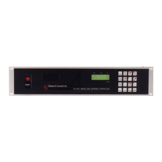
CONTROL-1500A (Specs pg1-2, Manual on pg3)
F E A T U R ES
TM
or optional control for
makes no additional or independent warranty.
purpose are disclaimed. We do our best to be accurate.
the "Answers" button at the DAWNco web site.
R e m o t e C o n t r o ll e d
A n t e n n a C o n t r o ll e r
f o r Si n g l e A x is A n t e n n as
!
Dual Speed
For fast slewing, fine positioning, user
programmable
!
RS-422 PC Control Interface
Automated control with many popular
packages; basic PC-control software is
included
TM
!
Adapti-Drive
Maintains stable speed with varying load
!
Solid-State Drive Circuitry
Provides reliable, quiet operation, rated at 5A
with over-current protection
!
Multi-Band Operation
Supports C, Ku and L-band satellites
Advertisement
Table of Contents
Troubleshooting

Summary of Contents for Dawn CONTROL-1500A
- Page 1 CONTROL-1500A (Specs pg1-2, Manual on pg3) R e m o t e C o n t r o ll e d A n t e n n a C o n t r o ll e r f o r Si n g l e A x is A n t e n n as...
- Page 2 determined by antenna beamwidth (as determined from antenna O P E R A T I O N A L O V E R V I E W size and the frequency band), satellite inclination, and a user specified maximum allowable error (in dB). STEP_TRACK mode The RC1500 was designed to provide years of reliable operation is active until a time is reached that corresponds to a segment of through the use of a heavy duty solid-state drive network coupled...
- Page 3 CONTROL-1500A Single Axis Antenna Controller Operator's Manual v 1.20 CONTENTS SUBJECT TO CHANGE Jan 29, 2004 DAWNco • 3340 S. Lapeer Rd • Orion, MI 48359-1320 • Ph (248) 391-9200 • Fax (248) 391-9207 • sales@DAWNco.com You are entitled to the manufacturer's limited express warranty, if any, that accompanies the product. DAWNco makes no additional or independent warranty.
-
Page 4: Table Of Contents
3.2.1 Antenna Motor Drive ....................13 3.2.2 Position Sense ......................14 3.3 Polarization Control .......................17 3.3.1 Configuring the CONTROL-1500A for Use in an Installation that Does Not Employ a Polarization Control Device....................17 3.3.2 Configuring the RC1500 for use with a Polarotor ............17 3.3.3 Rotating Feed with Potentiometer Position Feedback..........18... - Page 5 3.6 Signal Strength Display ....................26 3.6.1 Controller AGC Potentiometor Adjustment..............27 3.7 Programming Geostationary Satellites ................32 3.8 AutoPol..........................33 3.9 Installation and Setup Checklist..................34 Chapter 4 – Controller Operational and Programming Modes ..........36 4.1 MANUAL Mode......................36 4.2 AUTO Mode ........................37 4.2.1 Invalid Data ......................38 4.3 REMOTE Mode ......................39 4.4 LIMITS Mode .........................39 4.5 SETUP Mode.........................40...
- Page 6 6.1 SYSTEM ERROR CODES ....................54 LOW BATTERY ........................54 ANT LIMITS ........................54 POL LIMITS ........................54 ANT AZ/EL, ANT POL.......................55 AZ/EL COUNT ........................55 SLOW SPEED ........................55 AUTOPOL CFG ........................55 COMM PORT........................55 POL OPTIONS........................55 AZ/EL OPTIONS .......................55 6.2 OPERATIONAL TROUBLESHOOTING TIPS ...............55 Appendix A Expert Access and System Reset Code ..............58 Appendix A1 - Restoring Non-Volatile Memory ................59 Appendix A2 - Recovering From Unexpected Memory Upsets ..........61 Appendix C –...
- Page 7 Processor Board Schematic ....................91 Drive Board Schematic ......................92 Declaration of Conformity......................93 DAWNco • 3340 S. Lapeer Rd • Orion, MI 48359-1320 • Ph (248) 391-9200 • Fax (248) 391-9207 • sales@DAWNco.com...
-
Page 8: Chapter 1 Introduction
Chapter 1 INTRODUCTION The CONTROL-1500A antenna controller controls a single axis satellite antenna. The CONTROL-1500A interfaces to 36 volt actuators with single phase, pulse type position sense feedback. Two basic models are available, the CONTROL-1500A and CONTROL-1500B. The CONTROL-1500B can track inclined orbit satelliteswith either a single axis tracking mount or a single axis feed translation system. -
Page 9: Before You Begin
CONTROL-1500A Single Axis Antenna Controller Chapter 1 Introduction The Installation portion of the manual is comprised of Chapters 2 and 3. Chapter 2 explains the user interface and the basic operation of the unit. Chapter 3 guides the user through the physical installation and wiring of the unit as well as the initial software configuration. -
Page 10: Chapter 2 Basic Function Description
CONTROL-1500A Single Axis Antenna Controller Chapter 2 Basic Function Description Chapter 2 BASIC FUNCTION DESCRIPTION This chapter describes the controller's front panel layout, user interface and basic operation. When the user has completed this chapter, he or she should have an understanding of the various operating modes of the unit, and be able to use the keyboard and liquid crystal display (LCD) to navigate through those modes. - Page 11 CONTROL-1500A Single Axis Antenna Controller Chapter 2 Basic Function Description Figure 2.2 CONTROL-1500 Keypad An examination of the keyboard in figure 2.2 reveals that many of the keys have two or more labels. The function of each key is determined by the current operational mode of the controller.
-
Page 12: Changing Modes With The Mode Key
CONTROL-1500A Single Axis Antenna Controller Chapter 2 Basic Function Description This key toggles the antenna speed from FAST to SLOW and vice versa. ARROW KEYS - 2/4/6/8 These keys are used to manually jog the antenna in some modes. The left and down arrow keys jog the antenna one direction while the right and up arrow keys jog the antenna in the other direction. -
Page 13: Warranty
CONTROL-1500A Single Axis Antenna Controller Chapter 2 Basic Function Description MANUAL 1673 50 H GALAXY 6 F MAN MODE In manual mode you can: 1. Jog the antenna about the fundamental control axis using the ARROW KEYS 2. Toggle the speed from fast to slow (and vice versa) with the SPEED key. - Page 14 CONTROL-1500A Single Axis Antenna Controller Chapter 2 Basic Function Description REMOTE 1673 50 H GALAXY6 MODE In this mode the controller receives and acts on commands received via the communications port. This mode can only receive control if enabled via the Remote Enable CONFIG mode item.
- Page 15 CONTROL-1500A Single Axis Antenna Controller Chapter 2 Basic Function Description RESET JAMMED A/E-1: MODE This mode allows the user to examine the error status of the motor drive circuits and reset them if a fault has occurred. The status of the antenna drive is displayed on the top line below the ‘POS’...
-
Page 16: Mode Access
CONTROL-1500A Single Axis Antenna Controller Chapter 2 Basic Function Descriptions selected from non-volatile memory. A single resynch will realign all satellites stored in non- volatile memory. CONFIG AUTOPOL ENABLE:* 0-NO, 1-yes MODE This mode allows the user to view and enter configuration data into the controller. This data is stored in non-volatile memory and is used to set certain parameters and enable or disable various controller options. -
Page 17: Expert Access
CONTROL-1500A Single Axis Antenna Controller Chapter 2 Basic Function Description 1. REMOTE mode is only accessible when the Remote Mode Enable CONFIG mode item is set to 1. When enabled, REMOTE mode can be activated either via the MODE key or by the receipt of a command on the serial port. -
Page 18: Chapter 3 Installation/Setup
CONTROL-1500A Single Axis Antenna Controller Chapter 3 Installation/Setup 11 Chapter 3 INSTALLATION/SETUP This chapter guides the installer through the mechanical and electrical installation of the controller as well as initial software setup. This chapter describes the electrical connectors on the back panel of the controller, cabling requirements, installation of optional polarization control devices, antenna limits, and configuration of the antenna slow speed system. -
Page 19: Mechanical And Electrical Installation
CONTROL-1500A Single Axis Antenna Controller Chapter 3 Installation/Setu the data entry field, enter the 5 digit code described in section 2.5 to toggle the Expert Access flag on. This will allow access to the Reset Sys CONFIG mode item. 3. At the Reset Sys screen enter the same 5 digit code followed by the ENTER key. -
Page 20: Antenna Motor Drive
CONTROL-1500A Single Axis Antenna Controller Chapter 3 Installation/Setup 3.2.1 Antenna Motor Drive The antenna actuator motor drive is interfaced to the controller via the connector J2, terminals 4 and 6, labeled AZ1 and AZ2, respectively. Do not make any connections to the connector J2 terminals labeled EL1 and EL2. -
Page 21: Position Sense
CONTROL-1500A Single Axis Antenna Controller Chapter 3 Installation/Setup Wire Size → 16 AWG 14 AWG 12 AWG 10 AWG Motor Current ↓ 6 amps 8 amps A typical 36 volt actuator will draw 2 to 4 amps and will run at voltages down to about 12 volts. - Page 22 CONTROL-1500A Single Axis Antenna Controller Chapter 3 Installation/Setup output (connected to Sensor AZ +), and the green lead is the sensor ground connection which is tied to the Sensor AZ – terminal. With a reed switch type sensor, the alternating magnetic field causes a mechanical switch to make and break.
- Page 23 CONTROL-1500A Single Axis Antenna Controller Chapter 3 Installation/Setup Figure 3.2 Reed Sensor Diagram Figure 3.3 Hall Effect Diagram DAWNco • 3340 S. Lapeer Rd • Orion, MI 48359-1320 • Ph (248) 391-9200 • Fax (248) 391-9207 • sales@DAWNco.com...
-
Page 24: Polarization Control
3.2.2. Figures 3.2 and 3.3 show the connection of the Polarotor to the controller. The following table details the interface of a Polarotor to the CONTROL-1500A … CONTROL-2000 Connection Signal Description... -
Page 25: Rotating Feed With Potentiometer Position Feedback
3.3.3 Rotating Feed with Potentiometer Position Feedback With the RC2KPOL option, the CONTROL-1500A can control a 24 volt DC rotating feed with potentiometer feedback (400 ma max motor drive current). The RC2KPOL is frequently used to control a Seavey Engineering model 124 ESA rotating feed. - Page 26 CONTROL-1500A Single Axis Antenna Controller Chapter 3 Installation/Setup 2. Connect an ohm meter between the wiper of the pot (terminal 2 on the Spectrol or Contelec) and one of the other two terminals. Note that when the shaft position of the pot is near one of the pot's mechanical limits, the ohm meter will read either less than 25 ohms, or the value found in step 1.
- Page 27 Under no circumstances should a 5 conductor shielded cable be used to carry both the motor current and the potentiometer position sense signals. Figure 3.4 depicts the connection of a rotating feed device with the CONTROL-1500A. Note that the potentiometer interface cable’s drain wire is connected to the Signal Return terminal (1) of connector J4.
-
Page 28: Antenna Drive Polarity And Limits
CONTROL-1500A Single Axis Antenna Controller Chapter 3 Installation/Setup mode, the Expert Access flag has been reset. If this occurs, set the Expert Access flag as outlined in section 2.5. 3. In this step the polarity of the polarization motor and sensor wiring is checked. -
Page 29: Motor Drive Polarity
CONTROL-1500A Single Axis Antenna Controller Chapter 3 Installation/Setup NOT MOVE PAST A PHYSICAL LIMIT. NOTE ALSO THAT THE CW AND CCW POLARIZATION ADJUSTMENT KEYS ARE ACTIVE. 3.4.1 Motor Drive Polarity The antenna motor is connected as outlined in figures 3.2 or 3.3. To check the motor drive polarity, from LIMITS mode, depress the AZ CCW key and verify that the antenna moves counter-clockwise as seen by a user located above the antenna. - Page 30 CONTROL-1500A Single Axis Antenna Controller Chapter 3 Installation/Setup ANTENNA LATITUDE + DELTA … where DELTA is a small angle that varies with antenna latitude. Table 3.3 xx provides values for DELTA as a function of antenna latitude. The Latitude Angle is often adjusted with a threaded rod.
- Page 31 CONTROL-1500A Single Axis Antenna Controller Chapter 3 Installation/Setup Antenna Latitude Delta Angle (degrees) Latitude Angle Declination (degrees) (degrees) (degrees) 0.68 50.7 6.61 0.65 55.6 7.05 0.60 60.6 7.45 0.53 65.5 7.78 0.44 70.4 8.06 0.35 75.3 8.28 Table 3.4 Polar Mount Latitude and Declination Angles...
-
Page 32: Slow Speed Adjustment
CONTROL-1500A Single Axis Antenna Controller Chapter 3 Installation/Setup from both Ku and C band satellites, use Ku band satellites for making the adjustments as the antenna beamwidth will be narrower at Ku band. 5. Find a satellite that is at approximately the same longitude as the antenna. Motor the antenna so that the antenna is at its highest elevation angle. -
Page 33: Signal Strength Display
CONTROL-1500A Single Axis Antenna Controller Chapter 3 Installation/Setup set to 254 and slow speed is selected, the slow banner and a voltage code will be displayed, but the drive will move at fast speed and the voltage code will not change. -
Page 34: Controller Agc Potentiometor Adjustment
CONTROL-1500A Single Axis Antenna Controller Chapter 3 Installation/Setup The controller has the provision to process two channels of AGC information. This means that two receivers can be connected to the controller. The two channels are referred to as AGC1 and AGC2. Each channel has separate gain and offset potentiometer adjustments. The installer uses the pots to transform the receiver's AGC signal swing into a range of values which is easily measured by the controller. - Page 35 CONTROL-1500A Single Axis Antenna Controller Chapter 3 Installation/Setup 2. Jog the antenna off of the satellite so the antenna is looking at nothing. Measure and record the receiver's AGC voltage. In the description that follows, the term 'off satellite' will be used to refer to this case where the antenna is positioned well off of any satellite, looking at nothing.
- Page 36 CONTROL-1500A Single Axis Antenna Controller Chapter 3 Installation/Setup turns or until a faint click is audible. Similarly, rotate the SCALE pot clockwise 20 turns or until a faint click is audible. 6. In the next few steps of the procedure, the OFFSET and GAIN pots of the AGC channel(s)
- Page 37 CONTROL-1500A Single Axis Antenna Controller Chapter 3 Installation/Setup same AGC channel is used for both frequency bands, and therefore the OFFSET and GAIN pot adjustments for that channel must be made so as to accommodate both frequency bands. At the heart of the problem is the fact that the signal strength (as seen by the receiver's AGC circuits) will vary with the frequency band selected due to differences in antenna gain, LNB gain, and the differences in output power between C and Ku band satellites.
- Page 38 CONTROL-1500A Single Axis Antenna Controller Chapter 3 Installation/Setup 5b. If the receiver's AGC has NEGATIVE polarity and only one receiver is interfaced to the controller, connect a jumper from the controller's unused AGC input channel to connector J1, pin 11. From MANUAL mode use the Scroll Up/Down keys to examine the signal strength for the AGC channel which was not selected in step 3 above.
-
Page 39: Programming Geostationary Satellites
CONTROL-1500A Single Axis Antenna Controller Chapter 3 Installation/Setup found in step 2 (use the band specified at the end of the previous sentence). If both controller AGC inputs are utilized, record similar values for ‘RCV2 – on satellite – strong band’ ______ (C or Ku band) and ‘RCV2 – off satellite – weak band’ _____ (C or Ku band). -
Page 40: Autopol
CONTROL-1500A Single Axis Antenna Controller Chapter 3 Installation/Setup Setup mode is straightforward. When Setup mode is first invoked, the antenna jog keys and Scroll Up/Down keys are active. The jog keys are used to align the antenna with the satellite the user operator wishes to program into the controller’s non-volatile memory. -
Page 41: Installation And Setup Checklist
CONTROL-1500A Single Axis Antenna Controller Chapter 3 Installation/Setup (also referred to as ‘return’) and the other side connected to the AutoPol input. When the relay is active the AutoPol input is connected to ground - a low level input. When the relay is deactivated, the relay contacts open and the AutoPol input floats high due to the controller’s... - Page 42 CONTROL-1500A Single Axis Antenna Controller Chapter 3 Installation/Setup 6. Configure the Slow Speed Config mode item. See section 3.5 for setting the slow speed. For a standard 36 volt DC linear actuator with 30 to 40 pulses per inch, a slow speed value code of 140 to 180 is generally appropriate.
-
Page 43: Chapter 4 - Controller Operational And Programming Modes
CONTROL-1500A Single Axis Antenna Controller Chapter 4 Modes Function Description Chapter 4 – Controller Operational and Programming Modes The controller’s current mode is displayed in the lower right hand corner of the LCD. Each of the controller’s modes are members of either the Operational mode group or the or the Programming mode group. -
Page 44: Auto Mode
CONTROL-1500A Single Axis Antenna Controller Chapter 4 Modes Function Description displayed. Depressing the Scroll Up and/or Scroll Down keys will cycle between the display of AGC1, AGC2, and the greater of AGC1 or AGC2. When the greater of the two AGC inputs is displayed a blank character (‘ ‘) will be present to the left of the signal strength display field. -
Page 45: Invalid Data
CONTROL-1500A Single Axis Antenna Controller Chapter 4 Modes Function Description outside of the current limits for each of those axis, the antenna will display an INVALID DATA prompt. See section 5.2.1 for more information. 3. Select Polarization – If AutoPol is disabled, the user will be prompted to select a polarization... -
Page 46: Remote Mode
CONTROL-1500A Single Axis Antenna Controller Chapter 4 Modes Function Description Make sure that CC or CW is not displayed in the antenna position (POS) or polarization position (POL) fields. 3. The 24 VDC Rot Feed Config mode item was toggled after the satellite was programmed into the controller’s non-volatile memory. -
Page 47: Setup Mode
CONTROL-1500A Single Axis Antenna Controller Chapter 4 Modes Function Description ******************************* WARNING ***************************** THERE ARE NO RESTRICTIONS ON ANTENNA MOVEMENT WHEN IN THE LIMITS MODE - USE CAUTION! ************************************************************************** Here is the procedure for setting the limits. 1. Activate Limits Mode - Go to LIMITS mode. Section 2.2 describes Mode key operation. Hit the ENTER key to advance beyond the prompt message. - Page 48 CONTROL-1500A Single Axis Antenna Controller Chapter 4 Modes Function Description 1. When Setup mode is invoked the user is presented with the following prompt … ENTER TO PROCEED MODE TO EXIT SET MODE 2. After the ENTER key is hit, the user is presented with the following display …...
-
Page 49: User-Defined Satellite Names
CONTROL-1500A Single Axis Antenna Controller Chapter 4 Modes Function Description ADJST POL, SET H/V SET MODE To set the horizontal polarization, the operator should tune the receiver to a vertically polarized transponder and use the Pol CW and Pol CCW keys to null out, or minimize, received signal strength. -
Page 50: Reset Mode
CONTROL-1500A Single Axis Antenna Controller Chapter 4 Modes Function Description 913 220 USER MODE When the Enter key is hit, the controller will display the following screen … KEY IN SAT NAME MODE Note that the cursor is displayed under the '*' character. The Scroll Up and Scroll Down keys allow the user to select alphanumeric characters (A-Z, 0-9, hyphen (-), and space). -
Page 51: Delete Mode
CONTROL-1500A Single Axis Antenna Controller Chapter 4 Modes Function Description JAMMED Indicates that the antenna was commanded to move about the axis and no movement was detected by the controller. This indicates either that the antenna did not move when commanded to do so, or the sensor failed and the controller was not able to detect any movement (antenna or polarization). -
Page 52: Fix Mode
CONTROL-1500A Single Axis Antenna Controller Chapter 4 Modes Function Description DATA DELETED MODE FIX Mode SELECT SATELLITE GALAXY 6 MODE The FIX feature allows the position of a satellite stored in non-volatile memory to be loaded into the controller's current position counter. This feature is useful if a faulty position sensor or a noise impulse results in an errant position count. -
Page 53: Autopol
CONTROL-1500A Single Axis Antenna Controller Chapter 4 Modes Function Description accessible will be the AutoPol Enable, Remote Enable, and Expert On. When the Expert Access flag is set, access to the other CONFIG mode items can be further restricted by the value of a controlling Config mode item. -
Page 54: Slow Speed Code
CONTROL-1500A Single Axis Antenna Controller Chapter 4 Modes Function Description REMOTE ENABLE:1 0-NO, 1-yes MODE The Comm Address item selects the address of the communications port. Valid values for this parameter are 49 to 111. COMM ADDRESS: 50 49 – 111 MODE The Baud (100s) item selects the baud rate that the controller’s serial port will be initialized to. -
Page 55: Motor Drive Options
CONTROL-1500A Single Axis Antenna Controller Chapter 4 Modes Function Description 24vdc ROT FEED:0 0-NO, 1-yes MODE The following items set the controller's CW and CCW polarization limits when a rotating feed is installed. The procedure to determine these limits is given in section 3.3. Note that the CW limit must by definition be less than the CCW limit. - Page 56 CONTROL-1500A Single Axis Antenna Controller Chapter 4 Modes Function Description FST/SLO THRSH:80 0-99 CNTS MODE The Retry Attempts CONFIG mode item sets the maximum number of attempts which will be made to hit a target position (within 'Max Position Error’ counts - described below) during an automatic move initiated from AUTO mode.
-
Page 57: Signal Strength Parameters
CONTROL-1500A Single Axis Antenna Controller Chapter 4 Modes Function Description disabled. To DISABLE these features, make sure that the value entered for Fst Deadbnd DOES NOT end in '01' (i.e. when the value is divided by 100 the remainder is not 1), and that the value entered for Slo Deadbnd DOES end in either '00' or '50' (i.e. -
Page 58: Reset System Data
CONTROL-1500A Single Axis Antenna Controller Chapter 4 Modes Function Description and CONFIG mode items which can change the contents of the controller's non-volatile memory. When the Expert Access screen is displayed, the present state of the Expert Access flag is displayed in the data entry field. - Page 59 CONTROL-1500A Single Axis Antenna Controller Chapter 4 Modes Function Description Data Item or Condition Default Value User Assigned Value Baud (100s) … Communications port baud 9600 _______ rate Slow Speed _______ 24vdc ROT FEED … 24 volt DC rotating feed 0 –...
-
Page 60: Chapter 5 Specifications
CONTROL-1500A Single Axis Antenna Controller Chapter 5 Specifications Chapter 5 SPECIFICATIONS Inspect unit for any damage caused during shipping. If any exists, notify shipper immediately. PHYSICAL Size 19.0" x 3.5"H x 9.0"D (Rack) Weight 12.5 lbs. Temperature 0-50 o C Input Power 115/230 VAC, 50/60 Hz., 48 W (excluding... -
Page 61: Chapter 6 Troubleshooting/Alarm Codes
CONTROL-1500A Single Axis Antenna Controller Chapter 6 Troubleshooting/Alarm Codes Chapter 6 TROUBLESHOOTING/ALARM CODES This chapter covers error messages and system troubleshooting. Two types of error messages can occur: System errors, covered in 6.1, and Track Errors, in 6.2. System errors can occur at any time. -
Page 62: Ant Az/El, Ant Pol
CONTROL-1500A Single Axis Antenna Controller Chapter 6 Troubleshooting/Alarm Codes ANT AZ/EL, ANT POL These alarm messages indicate that an error has been detected for the axis referenced in the alarm message. When one of these alarms are detected, the axis is disabled. Go to RESET mode (section 4.6) to view the actual fault condition which was detected and to clear the fault. - Page 63 CONTROL-1500A Single Axis Antenna Controller Chapter 6 Troubleshooting/Alarm Codes When this occurs the controller is generally losing or gaining position counts for a given axis as the antenna moves about that axis. Please review the items mentioned in Section 3.2 - Azimuth and Elevation Position Sense.
- Page 64 CONTROL-1500A Single Axis Antenna Controller Chapter 6 Troubleshooting/Alarm Codes This error is usually caused by the horizontal and vertical polarizations for a given satellite being programmed at the same position. If you turn off the AutoPol function and the controller does not toggle the polarization position as the H and V keys are pressed in MANUAL mode, the polarization positions have probably been programmed at the same value.
-
Page 65: Appendix A Expert Access And System Reset Code
CONTROL-1500A Single Axis Antenna Controller Appendix A Expert Access and System Reset Appendix A Expert Access and System Reset Code A five digit code must be entered to reset the controller or toggle the controller’s Expert Access flag. The 5 digit code is 41758. Be sure to terminate the entry with the ENTER key. -
Page 66: Appendix A1 - Restoring Non-Volatile Memory
CONTROL-1500B Single Axis Antenna Controller Appendix A1 Restoring Non-Volatile Memory Appendix A1 - Restoring Non-Volatile Memory This appendix outlines a procedure which allows the user to restore the contents of non- volatile memory. A number of events can make this necessary, including: i. - Page 67 CONTROL-1500A Single Axis Antenna Controller Appendix A1 Restoring Non-Volatile Memory 8. In this step, the positions of the geostationary satellites are stored in non-volatile memory. Go to SETUP mode. Position the antenna on each of the satellites which were recorded in step 3 above.
-
Page 68: Appendix A2 - Recovering From Unexpected Memory Upsets
CONTROL-1500A Single Axis Antenna Controller Appendix A2 Unexpected Memory Upsets Appendix A2 - Recovering From Unexpected Memory Upsets The key to restoring the non-volatile memory is getting the azimuth and elevation limits and position counts right. The position counts are initialized to 30 when the east and down limits are set. -
Page 69: Appendix C - Rs-422 Serial Interface
7935) and is available from Research Concepts. This program can control the CONTROL-2000 and the CONTROL-1500A antenna controllers as well as the Standard Agile Omni model 830BR or the DX657 satellite receiver. This program runs under DOS and gives the user the ability to schedule antenna and receiver events. - Page 70 CONTROL-1500A Single Axis Antenna Controller Appendix C RS-422 Serial Interface Louth Automation: (415) 329-9498 M & C Systems: (408) 454-0396 DAWNco • 3340 S. Lapeer Rd • Orion, MI 48359-1320 • Ph (248) 391-9200 • Fax (248) 391-9207 • sales@DAWNco.com...
-
Page 71: Appendix D - The Rci Rs-422 Interface Specification
CONTROL-1500A Single Axis Antenna Controller Appendix D The RCI RS422 Interface Spec Appendix D - The RCI RS-422 Interface Specification Introduction The purpose of this document is to explain the key parameters needed by a user to interface to the RCI RS422 Interface. This interface is compatible with the SAbus and can be readily integrated into an existing SAbus network. - Page 72 CONTROL-1500A Single Axis Antenna Controller Appendix D The RCI RS422 Interface Spec RS-422 Protocol The interface is a multi-drop, balanced line, asynchronous, full-duplex communications link designed to interconnect equipment for remote control and switching applications. Products that are compatible can be linked together over a parallel-connected 4-wire circuit without regard to their particular function.
- Page 73 CONTROL-1500A Single Axis Antenna Controller Appendix D The RCI RS422 Interface Spec Figure 2 and 3 show RS-422 Master and Slave connections respectively. Data Format The data format supports the industry's standard asynchronous ASCII format with one start bit, eight data bits (7-bit ASCII with the 8th bit sent as even parity), and one stop bit. The ASCII control character subset 00-1F (hex) is reserved for message control.
- Page 74 CONTROL-1500A Single Axis Antenna Controller Appendix D The RCI RS422 Interface Spec Command messages (see Figure 4) begin with Start-of-text byte, STX, followed by a remote address, a command byte and multiple data bytes. The End-of-text byte, ETX, is sent following the last data byte, and the message is terminated by a checksum character.
- Page 75 CONTROL-1500A Single Axis Antenna Controller Appendix D The RCI RS422 Interface Spec through the ETX character. This forms a Longitudinal Redundancy parity check over the entire message. Message Timing The NAK or ACK reply does not signify that a function has actually taken place, but only that the message was received and understood.
- Page 76 CONTROL-1500A Single Axis Antenna Controller Appendix D The RCI RS422 Interface Spec Table 1. State Diagram Mnemonics ___________________________________________________________________________________ Mnemonics Description ___________________________________________________________________________________ Start-of-Text ASCII control character, used as a header in command messages to identify the beginning of a new message.
- Page 77 CONTROL-1500A Single Axis Antenna Controller Appendix D The RCI RS422 Interface Spec • State 3 (Slave Data State) if received address byte equals a slave's address. • State 1 (Slave Idle State) if received address byte does not equal a slave's address.
-
Page 78: Appendix E - Control- 1500A Communications Protocol
CONTROL-2000C Polar with all of the elevation related fields ignored.Two versions of the CONTROL-1500 are offered. The CONTROL-1500A is for use with polar mounts looking at geostationary satellitesThe CONTROL-1500 supports tracking of an inclined orbit satellite with a single axis mount whose axis of motion is aligned with the apparent motion of the satellite. - Page 79 CONTROL-1500B Single Axis Antenna Controller Appendix E Communications Protocol CONTROL-1500 ONLINE/OFFLINE To enable remote mode on the RC1500, the internal remote$mode$enable$flag must be set. This flag is set at the 'REMOTE MODE ENABLE' prompt in CONFIG mode. When this flag is set, remote mode can be entered in two ways.
- Page 80 CONTROL-1500B Single Axis Antenna Controller Appendix E Communications Protocol The SA Bus specification requires that command character 31h cause a device to return its status information. The reply to this command includes azimuth, elevation and polarization position, current satellite name, as well as limit, alarm and drive status information. The status poll command message consists of 5 bytes and the format is;...
- Page 81 CONTROL-1500B Single Axis Antenna Controller Appendix E Communications Protocol user_interface_position ... is the polarization position displayed on the display of the user interface. Note that the division defined above is an integer division. The result is rounded DOWN to the closest integer. Please see byte 32 of this command's reply message for more information on polarization position representations.
- Page 82 CONTROL-1500B Single Axis Antenna Controller Appendix E Communications Protocol byte 30: least significant nibble of alarm status - binary data 7 6 5 4 3 2 1 0 0 0 1 0 $ _ _ _ _ least significant nibble a a a a of the alarm code 3 2 1 0 byte 31:...
- Page 83 CONTROL-1500B Single Axis Antenna Controller Appendix E Communications Protocol Internal position values in range of 1 to 660 are scaled to display as a value of 0 to 98 on both the user interface and via bytes 24 and 25 of the device status poll reply.
- Page 84 CONTROL-1500B Single Axis Antenna Controller Appendix E Communications Protocol l band s s s s - - - - 0 0 0 0 track mode not active 0 0 0 1 track setup submode active 0 0 1 0 track auto mode entry 0 0 1 1 step track submode active 0 1 0 0...
- Page 85 CONTROL-1500B Single Axis Antenna Controller Appendix E Communications Protocol the peaking operation is completed. The reply to a go_to command will be an ACK. A polarization jog command that is received during a peaking operation will not be registered and executed later. The reply to the command will be a NAK.
- Page 86 Control-1500B Single Axis Antenna Controller Appendix E Communications Protocol positions associated with that satellite. The satellite name should be in capital letters, left justified and padded on the right with blanks in the sat_name/position field. Note that the satellite name must exactly match one in the controller's non-volatile memory. With this form of the command, the polarization field may contain either 'H', 'V', or ' ' (a blank, 20 hex or 32 decimal).
- Page 87 'E', 'W', 'D', 'U' or 'X'. 'E' or ‘D’ specifies counterclockwise (CCW) movement for the CONTROL-1500A and down movement for the CONTROL-1500B, 'W' or ‘U’ specifies clockwise (CW) movement for the CONTROL-1500A or up movement for the CONTROL-1500B. An 'X' specifies that the antenna stop moving. byte 4: speed This field specifies the jog speed, either 'F' (Fast) or 'S' (Slow).
- Page 88 CONTROL-1500B Single Axis Antenna Controller Appendix E Communications Protocol The reply to this command will be the same as the reply to the status poll query except the command code will be '34h'. Note that the NAK reply will be sent back to the host if autopol is enabled or if 'H' or 'V' is specified and there are no satellites available in the CONTROL-1500 memory.
- Page 89 control-1500B Single Axis Antenna Controller Appendix E Communications Protocol A C program has been written which allows a user to exercise the control-1500. The program runs on an IBM PC (or compatible - running DOS) and was designed to aid the software developer who is writing programs to control the control-1500.
-
Page 90: Appendix G Drive Transfer Function
CONTROL-1500A Single Axis Antenna Controller Appendix G Drive Transfer Function APPENDIX G Drive Transfer Function CONTROL-2000 Drive Transfer Function (Fast Speed) Output Drive Current (Amps) DAWNco • 3340 S. Lapeer Rd • Orion, MI 48359-1320 • Ph (248) 391-9200 • Fax (248) 391-9207 • sales@DAWNco.com... -
Page 91: Appendix H Electrical Diagrams
Appendix H Electrical Diagrams CONTROL-1500A Single Axis Antenna Controller APPENDIX H Electrical Diagrams Drive Board Layout DAWNco • 3340 S. Lapeer Rd • Orion, MI 48359-1320 • Ph (248) 391-9200 • Fax (248) 391-9207 • sales@DAWNco.com... -
Page 92: Processor Board Layout
Appendix H Electrical Diagrams CONTROL-1500A Single Axis Antenna Controller Processor Board Layout DAWNco • 3340 S. Lapeer Rd • Orion, MI 48359-1320 • Ph (248) 391-9200 • Fax (248) 391-9207 • sales@DAWNco.com... -
Page 93: Comm Port Wiring Legend
Appendix H Electrical Diagrams CONTROL-1500A Single Axis Antenna Controller Comm Port Wiring Legend DAWNco • 3340 S. Lapeer Rd • Orion, MI 48359-1320 • Ph (248) 391-9200 • Fax (248) 391-9207 • sales@DAWNco.com... -
Page 94: Rc1Kadp Conversion
Appendix H Electrical Diagrams CONTROL-1500A Single Axis Antenna Controller RC1KADP Conversion DAWNco • 3340 S. Lapeer Rd • Orion, MI 48359-1320 • Ph (248) 391-9200 • Fax (248) 391-9207 • sales@DAWNco.com... -
Page 95: Rc1Kadp Schematic
Appendix H Electrical Diagrams CONTROL-1500A Single Axis Antenna Controller RC1KADP Schematic DAWNco • 3340 S. Lapeer Rd • Orion, MI 48359-1320 • Ph (248) 391-9200 • Fax (248) 391-9207 • sales@DAWNco.com... -
Page 96: Rc2Kpol Schematic
Appendix H Electrical Diagrams CONTROL-1500A Single Axis Antenna Controller RC2KPOL Schematic DAWNco • 3340 S. Lapeer Rd • Orion, MI 48359-1320 • Ph (248) 391-9200 • Fax (248) 391-9207 • sales@DAWNco.com... -
Page 97: Rc2Khpp Schematic
Appendix H Electrical Diagrams CONTROL-1500A Single Axis Antenna Controller RC2KHPP Schematic DAWNco • 3340 S. Lapeer Rd • Orion, MI 48359-1320 • Ph (248) 391-9200 • Fax (248) 391-9207 • sales@DAWNco.com... - Page 98 Appendix H Electrical Diagrams CONTROL-1500A Single Axis Antenna Controller Processor Board Schematic DAWNco • 3340 S. Lapeer Rd • Orion, MI 48359-1320 • Ph (248) 391-9200 • Fax (248) 391-9207 • sales@DAWNco.com...
- Page 99 Appendix H Electrical Diagrams CONTROL-1500A Single Axis Antenna Controller Drive Board Schematic DAWNco • 3340 S. Lapeer Rd • Orion, MI 48359-1320 • Ph (248) 391-9200 • Fax (248) 391-9207 • sales@DAWNco.com...
- Page 100 CONTROL-1500A Single Axis Antenna Controller Declaration of Conformity Declaration of Conformity Application of Council Directive: 72/23/EEC; 89/336/EEC Standards to which conformity is declared: EN-55022:1991, EN 50082-2, EN60950 Type of Equipment: Satellite Antenna Controllers CONTROL-2000A Model No’s.: Year of Manufacture: 1998...
Need help?
Do you have a question about the CONTROL-1500A and is the answer not in the manual?
Questions and answers