Table of Contents

Related Manuals for ETC MATRIX MK. II


Summary of Contents for ETC MATRIX MK. II
- Page 1 MATRIX MK. II DIMMING SYSTEM User Manual Version: 3.99 Copyright © Electronic Theatre Controls, Inc. All Rights reserved. Product information and specifications subject to change. Part number: 7540M1200-3.99 Rev. A Released: May 2010...
- Page 2 Matrix®, Matrix Mk2®, DimSTAT®, are either registered trademarks or trademarks of Electronic Theatre Controls, Inc. in the United States and other countries. All other trademarks, both marked and not marked, are the property of their respective owners.
-
Page 3: Table Of Contents
T a b l e o f C o n t e n t s Introduction ............1 Congratulations ..............1 Using this Manual..............1 Chapter 1 Overview ............3 System Components ............2 Processor ................2 Dimmer Monitoring Interface Overview ......3 Dimming System features ........... - Page 4 C o n t e n t s To set up a serial address ........14 Ethernet ..............14 To set up the dimmer IP address ......14 To set up the dimmer subnet mask ......15 To set up the dimmer gateway address ....15 To set up the merger IP address ......
- Page 5 Check ventilation ............ 31 Return to factory settings ........31 Factory defaults ............32 Chapter 4 Service ............43 Contacting ETC about Equipment Problems ......Changing Rack Modules ............Regular inspection ..............Check ventilation system ........... Annual inspection ............Fault finding ................
-
Page 7: Introduction
I n t r o d u c t i o n Congratulations... on the purchase of an ETC Matrix® MkII system. Matrix MkII continues ETC's tradition of providing the highest quality products for the entertainment lighting market. Using this Manual This manual describes the general operation and programming information for the Matrix Mk.II dimming system. -
Page 8: Overview
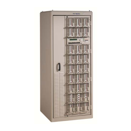
C h a p t e r 1 O v e r v i e w System Components The Matrix MkII dimming system consists of Matrix Mk.II racks, a Matrix Processor per rack, and various dimmer module types. A module may contain an SCR dimmer or a sine wave dimmer, but in addition, a module may contain only a circuit breaker, a group of relays for switching either conventional lighting or HMI sources, dimmers enhanced for Fluorescent loads, or may contain no electronics at all. - Page 9 There are 4 styles of cabinet for either 6-way or 4-way configurations, with or without swing frame (front access only). All are in standard ETC colours except where shown: 1600mm (h) x 800mm (w) x 800mm (d) swing frame, 4- or 6-way for 18 modules...
-
Page 10: Dimmer Monitoring Interface Overview
DMX start address per unit, DMX OK, line voltage, current per channel(with most modules), dimmer curve, response time, max. setting, type of fault reported (temperature, overload etc.), date and time of fault. It is possible to set the dimmer curve, start address and pre-heat from DimSTAT software on the PC. -
Page 11: Dimming System Features
DimSTAT offers interrogation facilities for each dimmer in the system at any time. To check the mains supply voltage, load current, temperatures etc, simply select a dimmer and view the data in the main screen. - Page 12 expense. Smaller transformers and backup generators can be purchased, offering great savings. Environmentally friendly: Providing a pure sinewave, SineWave technology avoids the peak currents which stress filaments and also eliminates harmonic currents which can affect other equipment and cause transformers to overheat. Cables and generators also benefit - with a pure sinewave supply, the infrastructure does not have to be overrated (usually 40% excess for normal dimming systems).
-
Page 13: Basic Navigation
C h a p t e r 2 B a s i c N a v i g a t i o n This section covers the functions and configuration of the Matrix Mk.II processor. It is possible to password protect areas of the configuration facility, and this is explained later, but for simplicity the details given here do not require password entry. - Page 14 The processor’s functionality is available with DimSTAT and is generally faster and easier to perform through DimSTAT using a PC using shortcuts to the Matrix’s setup features, but for the purpose of this handbook the differences in using DimSTAT are not described in detail.
- Page 15 Dimmer Module User Interface Local control for each dimmer module is included within the Processor, and no direct access is required with the module to view and adjust settings. However, each module includes slave indicators and an info button for convenience. When the interrogate button is pressed (message icon above the LED column) the Processor LCD panel and controls are routed to the selected module.
-
Page 16: Configuration Procedures
C h a p t e r 3 C o n f i g u r a t i o n P r o c e d u r e s Initial settings Some settings for the Matrix rack are made during installation only, and many of the channel configuration settings may only rarely be changed after the commissioning period. -
Page 17: Setup Schemes For Channels And Dmx
SELECT LOAD SELECTION DEVICE 12 LOAD: 4 x 3KW EDIT CANCEL SAVE Press EDIT. Use the rotary encoder to select the channel configuration of the device: 4 x 3kW 2 x 5kW 1 x 12kW Press SAVE (to record the changes and return to the home screen) or CANCEL (to leave the previous settings unchanged, and return to the home screen). -
Page 18: Dmx Programming
DMX programming Each channel in a Matrix device is assigned a DMX channel number from either DMX-1 or DMX-2 signal inputs. The two numbers can be the same or different, as required, and a feature is provided to set sequential number groups (‘Start’ addressing) instead of individual settings. -
Page 19: Dmx A/B Arbitration
encoder will increment the address number clockwise, and reduce the number anti-clockwise, with a roll-over at the 512-0 point. If START has been selected, only one number per DMX line is permitted. This is the number for dimmer channel 1 in the first device, and the remaining dimmers are automatically addressed in sequential order. -
Page 20: To Set Up A Dmx Backup Preset
Press SAVE to leave the menu and record the changes or CANCEL (to leave the previous settings unchanged and to return to the previous screen). Repeat the procedure for DMX-2. Note: If BACKUP has been set, do not forget to pre-set the relevant DMX backup states. To set-up DMX Backup preset: Select PRESETS. -
Page 21: Dmx Lamp Features
Lamp features Matrix sine wave technology offers two additional features to enhance lamp performance; Lamp Tuning and Lamp Saver. Lamp Tuning is a global feature which provides a load learning facility whereby the Matrix dimmer records the current after the lamp has been set to between 90-100% for 3 seconds. -
Page 22: Network Settings
Matrix Mk.II dimmers are prepared for use with Ethernet data distribution for dimmer signals and DimSTAT communications Dimmers may be controlled using Streaming ACN (ANSI E1.31), which is the level transport in ETC's Net3 networks.. Two sets of addresses need to be set up: IP, subnet and gateway addresses for the Ethernet connection for reporting and configuration used by DimSTAT, and similar settings for the Merger for Streaming ACN. - Page 23 <<<<< >>>>>> EDIT CANCEL SAVE Use the rotary encoder to choose the address number and press >>>> or <<<< to tab other 3-digit groups. Press ENTER to leave the menu, then either SAVE (to record the changes) or CANCEL (to leave the previous settings unchanged). To set-up the Ethernet subnet mask for DimStat communications: Select INSTALL from the home menu Press DOWN or UP or use the rotary encoder to choose ETHERNET SETUP...
-
Page 24: To Set Up The Merger Subnet Mask
SELECT MERGER ETHERNET GATEWAY ADDRESS IP ADDRESS [010] <<<<< >>>>>> EDIT CANCEL SAVE Use the rotary encoder to choose the address number and press >>>> or <<<< to tab other 3-digit groups. Press ENTER to leave the menu, then either SAVE (to record the changes) or CANCEL (to leave the previous settings unchanged). -
Page 25: To Set Up The Merger Gateway Address
Use the rotary encoder to choose the address number and press >>>> or <<<< to tab other 3-digit groups. Press ENTER to leave the menu, then either SAVE (to record the changes) or CANCEL (to leave the previous settings unchanged). To set-up the merger gateway address: Select INSTALL from the home menu Press DOWN or UP or use the rotary encoder to choose MERGER ETHERNET... -
Page 26: Channel Settings
Individual dimmers may be setup to have specific characteristics for a particular application, such as maximum and minimum level settings, non-dim operation, default fade in and fade out times etc. Maximum & Minimum levels It is possible to affect the output range of a dimmer by setting a minimum level and (or) a maximum level. -
Page 27: Dimmer Curves
LIN = linear relationship (standard) BBC = BBC specification SLAW = S-Law INV = inverted (control = zero, dimmer = full etc.) TVE = TVE television specification FLU3 = Fluorescent (minimum 30%) LIN5 = Linear (offset at 50%) -
Page 28: Non-Dim Operation
CONFIGURE CHANNEL PARAMETERS MIN% MAX% T-IN T-OUT CURVE I/O PRIOR 00.05 00.05 [LIN] NO NO EDIT CANCEL SAVE Use the <<<< and >>>> buttons, choose CURVE [enabled when square brackets are shown] and set it to the response required. Using the UP and DOWN buttons to address other channel numbers (unless all dimmers are being set-up together). -
Page 29: To Set Up Priority Channels
is not exceeded. This is achieved by setting the dimmer channel to “priority”, and it will then ignore any instruction to reduce level if the maximum demand is exceeded. To set-up maximum current levels: Select INSTALL from the home menu Press DOWN or UP or use the rotary encoder to choose SELECT LINE PARAMETERS menu. -
Page 30: Current Limitation
To switch on current limitation: Select INSTALL from the home menu Press DOWN or UP or use the rotary encoder to choose GENERAL SETTINGS menu. Press SELECT. Press DOWN or UP or use the rotary encoder to choose CURRENT LIMITATION menu. Press SELECT. The screen shows: GENERAL SETTINGS CURRENT LIMITATION: [OFF]... - Page 31 measured voltages using the rotary encoder. With the correct voltage showing in the square brackets, it is then possible to calibrate each line individually. Press SAVE to leave the menu and record the changes or CANCEL (to leave the previous settings unchanged).
-
Page 32: To Set Voltage Regulation
To set voltage regulation Select INSTALL from the home menu. Press DOWN or UP or use the rotary encoder to choose GENERAL SETTINGS. Press DOWN or UP or use the rotary encoder to choose VOLTAGE REGULATION menu. Press SELECT and the screen shows: GENERAL SETTINGS VOLTAGE REGULATION: [OFF]... -
Page 33: Start Mode
CONFIGURE CHANNEL PARAMETERS MAX% T-IN T-OUT CURVE I/O PRIOR PHASE 00.05 00.05 NO [OFF] <<<< >>>> CANCEL SAVE Use the <<<< and >>>> buttons, choose PHASE [enabled when square brackets are shown] and set it to either OFF for normal operation, or ON if the dimmer being used for other types of loads Using the UP and DOWN buttons to address other channel numbers (unless all dimmers are being set-up together). -
Page 34: Passwords
T-IN T-OUT CURVE I/O PRIOR PHASE MODE 00.05 00.05 LIN NO NO OFF [BASIC] <<<< >>>> CANCEL SAVE Use the <<<< and >>>> buttons, choose MODE [enabled when square brackets are shown] and set it to: BASIC, SOFT START, BURST, PROPortional or BLINK Using the UP and DOWN buttons to address other channel numbers (unless all dimmers are being set-up together). -
Page 35: Presets And Manual Control Functions
Preset and manual control functions The Matrix Mk.II system has a total of 7 digital switch functions which can be accessed through RS485 touch-panels. Options include fading or switching to a preset state. The setting up is in two steps; capturing the dimmer levels and setting the switch functions. -
Page 36: Manual Dimmer Control
If the presets are being set up for the first time, or significantly altered, it may be appropriate to erase all previous settings to start afresh as follows: Select INSTALL from the home menu Press DOWN or UP or use the rotary encoder to choose GENERAL SETTINGS menu. -
Page 37: Local Fault Reporting
Local fault reporting If a discrepancy in the normal operating parameters is registered, the Matrix device will display a red LED for the faulty channel and the Processor will report the potential fault. The CHECK light illuminates if a fault is recorded, the STATUS display changes from OK to CHECK, and any circuit errors are reported on the screen above the channel number affected as follows: L1: 245V-38A... -
Page 38: To Analyse Dimmer Status And Performance
To analyse dimmer status and performance Select INSTALL from the home screen Press DOWN or UP or use the rotary encoder to choose VIEW CHANNEL DATA menu. Press SELECT. The screen shows: LIVE CHANNEL DATA DEVICE 12 DMX-1 DMX-2 ACTUAL STAT. -
Page 39: Firmware Update
Matrix: Version 01.36 T. 8803uS Merger: Version 01.06 F/E 39045/ Device 01: Version 01.44 1654 RESET FRAMES DEV- DEV+ HOME Use DEV- and DEV+ to view device settings in sequence. Press HOME to leave the menu and to return to the home menu. Firmware Update The processor has a feature to update dimmers and the Ethernet merger with firmware. -
Page 40: Return To Factory Settings
parts of the dimmer devices, including the front panel illumination until such time that the DMX signal is re-established (as soon as the control desk is switched on). To set the dimmer device to ‘Sleep’ mode Select INSTALL from the home menu. Press DOWN or UP or use the rotary encoder to choose GENERAL SETTINGS menu. - Page 41 DMX-1 FAIL: reset DMX-2 ADDRESS: DMX-2 BACKUP: all 00 DMX-2 FAIL: reset DMX SYSTEM: individual DMX MINIMUM RESET: FREQUENCY: 50Hz LAMP SAVER LAMP TUNING LOAD SELECTION: all 2.5kW MANUAL PRESETS: all 00 MAXIMUM: 100% MINIMUM: MODE basic NON-DIM (I/O) PASSWORDS: all 0000 PC ADDRESS: PHASE...
-
Page 42: Service
C h a p t e r 4 S e r v i c e Contacting ETC Americas United Kingdom Electronic Theatre Controls Inc. Electronic Theatre Controls Ltd. Technical Services Department Technical Services Department 3031 Pleasant View Road 26-28 Victoria Industrial Estate... - Page 43 The effectiveness of all external connections, circuit protection devices, RCBOs etc. should also be checked regularly and at the annual inspection time. The RCBO can be tested by simply pressing the red test button to trip the circuit. Fault finding...
- Page 44 temperatures of adjacent devices. Also check the temperature for high ambient temperature. Over voltage alarm The dimmers affected by either an over or under-voltage condition will report the problem and will then shut down until the voltage returns to the specified range. This is to protect the loads from high voltages which would affect the life of the lamps connected.
- Page 45 A p p e n d i x A P r o c e s s o r m e n u s F1 SET DMX Set DMX This menu sets the DMX address for each channel or a start address for the channels in each module.
- Page 46 General settings This is the main system menu for general operating features: DMX address settings [individual or joined] Channel configuration settings [individual or joined] DMX 1 fail [reset, hold or backup] DMX 2 fail [reset, hold or backup] ...
- Page 47 A p p e n d i x B S c h e m a t i c d i a g r a m...
- Page 48 Service: (Americas) service@etcconnect.com (UK) service@etceurope.com (DE) techserv-hoki@etcconnect.com (Asia) service@etcasia.com Web: www.etcconnect.com Copyright © 2005 ETC. All Rights Reserved. Product information and specifications subject to change. 7540M1200-1.0.0 Rev A Released 01/2006 ...
Need help?
Do you have a question about the MATRIX MK. II and is the answer not in the manual?
Questions and answers