Table of Contents
Advertisement
User Manual
Version 2.1
C o p y r i g h t © E le c tr o n i c T h e a t r e C o n t r o l s , I n c .
A l l R i g h t s r e s e r v e d .
P r o d u c t in f o r m a t i on a n d s p e c i f i c a t i o n s s u bj e c t t o c h a n g e .
P a r t N u m b e r : 7020M1200-2.1.0 R e v A
R e le a s ed : 2 0 0 9 - 0 6
Advertisement
Table of Contents

Related Manuals for ETC SmartPack


Summary of Contents for ETC SmartPack
- Page 1 User Manual Version 2.1 C o p y r i g h t © E le c tr o n i c T h e a t r e C o n t r o l s , I n c . A l l R i g h t s r e s e r v e d .
- Page 2 ® ® ET C , S ma r t P a c k ® , S m a r t S w it c h ™ , a n d S m a r t L i n k a r e e i t h e r r e g i s t e r e d t r a d e m a r k s o r t r a d e m a r k s o f E l e c tr o n i c T he a t r e C o n t r o l s , I n c .
-
Page 3: Table Of Contents
Standard Features ........2 SmartPack Wall Mount ........3 SmartPack 19”... - Page 4 Service ..........22 Contacting ETC about Equipment Problems ....22 Maintenance.
-
Page 5: Introduction
SmartPack system, please contact ETC Technical Services at the office nearest you. U s i n g t h i s M a n u a l This manual contains information on the basic features and configuration for the SmartPack dimming pack with SmartLink™ enabled, wall station integration and maintenance procedures. -
Page 6: Overview
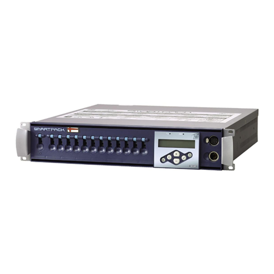
Overview SmartPack’s are designed to provide SCR-based, professional quality dimming packaged for portable, touring and permanent installations. ETC offers three versions of the SmartPack including the SmartPack 19” Portable Pack, SmartPack Touring Systems, and the SmartPack Wall Mount unit. Standard Features •... -
Page 7: Smartpack Wall Mount
The SmartPack Wall Mount unit with SmartLink enabled provides total versatility and convenience for venues requiring low profile permanently installed dimming. The SmartPack Wall Mount unit may be installed with or without other system components, ensuring the lowest possible cost ownership. In addition, a rack mount kit is available for installing the unit into an equipment rack. -
Page 8: Smartpack 19" Portable
CE marked SmartPack Portable dimming packs are available with either three 25A dimmers, six 15A dimmers, or twelve 10A dimmers. In addition the SmartPack 19” Portable pack is available with a wide variety of output panel options to fit industry needs. -
Page 9: Smartpack Touring System
The SmartPack Touring system offers small compact design built to travel. Standard UL Touring rack provides room for two or four SmartPack dimmer packs with the similar output panel options as available in the SmartPack 19” Portable pack. The UL SmartPack Touring system is SmartLink™... -
Page 10: Menu's And Configuration
Power Switch Use the Standby/Control power switch to start up and shut down operation of the SmartPack. When the breaker is in the “On” position, the blue Power LED is illuminated indicating the power is on. W A R N I N G : When the Standby/Control power switch is in the “Off”... -
Page 11: Lcd Display
I n i t i a l P o w e r U p D i s p l a y The first time you apply power to the SmartPack you will be asked to choose a language for the operating system. The language options will cycle through the following four options at three second intervals. -
Page 12: Normal Menu Structure
N o r m a l M e n u The normal menu is used to view system status and to set the DMX start address for SmartPack. The start address range is determined by the size of your SmartPack. DMX Start Address range:... -
Page 13: Advanced Menu Structure
D M X DMX Start Address The start address range is determined by the size of your SmartPack. When a DMX Start Address is selected as the active DMX Mode, the DMX range will be displayed on the LCD. DMX: 001 > 012... -
Page 14: Presets
P r e s e t s SmartPack features up to 32 built-in presets which can be recalled without the need of any external control system. For SmartLink enabled systems with a LinkPower supply installed, up to four 5 or 10 button preset stations may be used for remote recall of the built in presets and sequence. -
Page 15: Sequencer
S e q u e n c e r The built in sequencer in SmartPack plays a series of recorded presets sequentially. The order of execution is based on the first preset and the length is determined by the number if steps configured for the sequence. -
Page 16: Dimmer Curves
“S”. D i m m e r C u r v e s SmartPack is capable of dimming multiple load types including incandescent, low voltage and 2-wire fluorescent. SmartPack provides five user-selectable dimmer output curves to choose: •... -
Page 17: Emergency
E m e r g e n c y SmartPack is provided with a emergency contact input. When an active emergency contact is received all non-emergency dimmers in the SmartPack are forced off while all user- selected emergency dimmers energize to full. - Page 18 Assign Station Master One SmartPack in a system with wall stations installed should be configured as the “Station Master”. The station master tracks and updates button LED states for connected wall stations when preset or sequence changes occur. In addition the station master sends host messages to other SmartLink enabled SmartPack dimmer packs in the system.
-
Page 19: General Settings
G e n e r a l S e t t i n g s The General Settings menu is used to configure standard features of your SmartPack dimmer pack including: Set Language Multiple language options to choose from: •... -
Page 20: Diagnostics
Normal - the SmartPack powers up with both presets and the sequencer de-activated. • Previous State - powers up the SmartPack with the preset or the sequence active that was running during the previous session. This feature allows unattended operation through power blackouts. -
Page 21: Smartlink™ Enabled
SmartLink network and specific host messages. N o t e : The SmartPack Portable dimmer packs do not share the same I/O panel as the SmartPack Wall Mount. Utilize the RJ45 connectors located on the rear panel of the portable unit for SmartLink In and Thru. -
Page 22: Definitions
Definitions • Host Product - any SmartPack, SmartSwitch, Unison DRd with SmartLink or Sensor+ with SmartLink within a system that sends specific host messages to other SmartLink enabled products in the system for preset and sequence synchronization. • Station Master - any SmartLink enabled host product, with a LinkPower Supply (S-LPS) or Station Power Module (S-SPM) installed that is configured via the menu to control wall stations. -
Page 23: Pack Synchronization
If “Preset 1” is activated from the facepanel of a SmartPack: That SmartPack will act as the host product and send its host messages to the other SmartLink enabled products in the system to activate “Preset 1”. The preset will activate with the same fade up time, hold time, and fade down time as sent from the host product. -
Page 24: Stations
Contact ETC for assistance. A LinkPower supply must be installed into one SmartPack Wall Mount and is required to operate up to four wall stations per SmartLink system. The LinkPower supply is available factory installed or as a kit (S-LPS) for field installation. -
Page 25: Record A Preset From A Wall Station
It is possible to record a preset from a wall station if “Remote Record” has been enabled in the station master. See “Remote Record” on page 14. All SmartPack and SmartSwitch products on the SmartLink network will record the current output levels for the preset that is assigned to that button. -
Page 26: Service And Maintenance
If you are having difficulties, your most convenient resources are the references given in this manual. To search more widely try the ETC web site at www.etcconnect.com. If none of these resources is sufficient, contact ETC Technical Services directly at one of the offices listed below. -
Page 27: Maintenance
R e p l a c e m e n t P a r t s Two different fuses are used in three places on the SmartPack control board. Field replacements are available by ETC or may be purchased at your local electrical supply house. -
Page 28: Linkpower Supply Kit
SmartLink) in the system must have a LinkPower Supply or Station Power Module installed for wall station power. Due to the similar design for the SmartPack Wall Mount and the SmartSwitch Relay Panel control terminations, the following instructions may be used for either product. -
Page 29: Appendix B Menu Flow Chart
Appendix B Menu Flow Chart This appendix contains the SmartPack menu structure. Menu Flow Chart... - Page 30 SmartPack User Manual...
- Page 31 Menu Flow Chart...
- Page 32 Hong Kong Room 1801/F, Tower I Phase 1, Enterprise Square, 9 Sheung Yuet Road, Kowloon Bay, Kowloon, Hong Kong Tel +852 2799 1220 Fax +852 2799 9325 Service: (Americas) service@etcconnect.com (UK) service@etceurope.com (DE) techserv-hoki@etcconnect.com (Asia) service@etcasia.com Web: www.etcconnect.com Copyright © 2009 ETC. All Rights Reserved. Product information and specifications subject to change. 7020M1200-2.1.0 Rev A Released 2009-06...
Need help?
Do you have a question about the SmartPack and is the answer not in the manual?
Questions and answers
How to check the fuses due to lights being out
To check the fuses on an ETC SmartPack when the lights are out, follow these steps:
1. Remove Power: Turn off and disconnect power from the SmartPack unit.
2. Remove Front Cover: Take off the front cover and detach the ground wire.
3. Locate Fuses: Identify the fuses on the control board at locations F1, F2, and F3.
4. Inspect Fuses: Check if any fuse is blown. The fuses used are:
- F1 and F2: 0.125A 250V F 5x20mm (ETC part number F113-F)
- F3: 0.500A 250V F 5x20mm (ETC part number F112-F)
5. Replace if Necessary: If a fuse is blown, replace it with the correct type.
6. Reassemble and Restore Power: Reattach the ground wire, reinstall the front cover, and restore power to the unit.
If issues persist, contact ETC Technical Services for further assistance.
This answer is automatically generated