
Subscribe to Our Youtube Channel
Related Manuals for INOXPA DCS


Summary of Contents for INOXPA DCS
- Page 1 INSTALLATION, SERVICE AND MAINTENANCE INSTRUCTIONS TWIN SCREW PUMP Original Manual 01.531.30.01EN (0) 2021/09...
- Page 2 Telers, 60 17820 – Banyoles (Girona) Hereby declare under our sole responsibility that the machine TWIN SCREW PUMP Designation Type DCS 1B2, DCS 1B3, DCS 2B2, DCS 2B3, DCS 3B2, DCS 3B3, DCS 4B2, DCS 4B3 IXXXXXX IXXXXXX XXXXXXXXXIIN XXXXXXXXXIIN...
-
Page 3: Table Of Contents
7.4. Pump filling ..............................24 7.5. Pump starting .............................. 24 7.6. Switch off ..............................25 7.7. Working check............................. 25 7.8. CIP/SIP procedures ............................ 25 7.9. COP (cleaning out of place) procedure ...................... 26 8. Maintenance INOXPA S.A.U. 01.531.30.01EN · (0) 2021/09... - Page 4 9.2. Remove the pump from the group ......................33 9.3. Disassembly wet side components and mechanicals seals ............... 34 9.4. Assembly screw CW, screw CCW and mechanical seals ................38 9.5. Assembling the screws ..........................43 9.6. Tightening torque table ..........................44 INOXPA S.A.U. 01.531.30.01EN · (0) 2021/09...
-
Page 5: General Information
For this reason, it CANNOT be used for situations different from the ones specified on the confirmation. In case of working conditions change, it is necessary to keep in touch with INOXPA, which decline every kind of responsibility for uses different from those provided for by the contract. -
Page 6: Warranty
It is expressly forbidden to use the pump for staff lacking the required qualifications. The pump must be used only for the intended conditions of use in the specific purchase for which INOXPA ordered the execution, selected construction materials and performed the operation tests that make the pump snugly against the claims. -
Page 7: Pump Nameplate
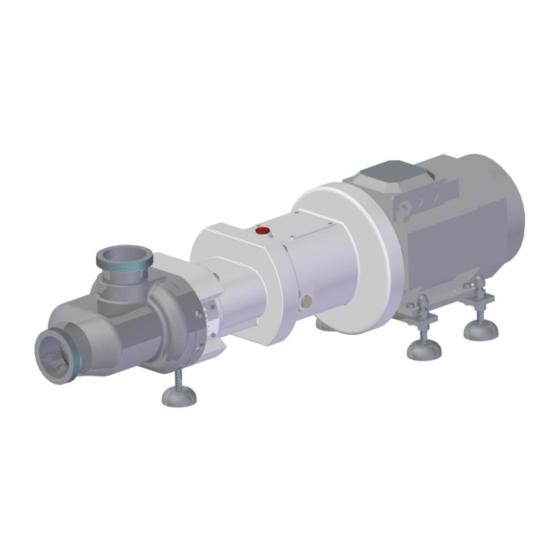
Fig. 3 – Pump on baseplate • Pump with flange connection. This pump version has got the drive unit flange-mounted directly to the gear casing and the levelling feet to place the pump at the required height: INOXPA S.A.U. 01.531.30.01EN · (0) 2021/09... - Page 8 The types of pump correspond to the scope specified in the order of the pump. When the pump is received, ensure that it is complete, check on the packing the lack of damages due to the transport and report immediately any defect or damage to the delivery company. INOXPA S.A.U. 01.531.30.01EN · (0) 2021/09...
-
Page 9: Design
3.2. PUMP ON BASE PLATE The pump may be provided with a base plate, these are the main parts: Fig. 6 –Indication of the main components of the pump with base plate (example) INOXPA S.A.U. 01.531.30.01EN · (0) 2021/09... -
Page 10: Pump Operations
4. Baseplate 3.3. PUMP OPERATIONS DCS pumps are volumetric devices fitted with two screws without contact between rotating parts. The synchronism between the rotors is ensured by a timing gear located outside the bearing casing. The medium goes into the pump casing from the suction body and it is inspired by the screws and pushed toward the discharge casing. -
Page 11: Safety
Safety 4. Safety Do not use the DCS pumps outside the prescribed limits contractually without the express consent of the INOXPA. The unauthorized use outside of the pressure and temperature limits may cause the deterioration of the seals, the binding and the explosion of the pump. Products with a viscosity higher than those prescribed by the contract can cause overheating of the pump. -
Page 12: Mechanical Risks
• The electrical display must be realized in conformity with the current regulations dispositions, all the electrical net connections must be done by an authorized installer. The installer has to assure the derivation suitability from the electrical net and then doing all the connection respecting the current regulations. INOXPA S.A.U. 01.531.30.01EN · (0) 2021/09... -
Page 13: Thermal Risks
• Close to the pump: noise pressure level to be measured and evaluated after the installation. • Risk of electrocution when next to electric panels (if they are in use). There may be additional risks. INOXPA S.A.U. 01.531.30.01EN · (0) 2021/09... -
Page 14: Carriage, Lifting And Storage
• Check that on the pump and the equipment provided with it there is a lack of visible damages. If there are damages to the pump and the equipment provided with it, contact immediately INOXPA to verify the pump function. - Page 15 90°. IT IS FORBIDDEN every pump’s movement or move some parts of its difference from what above described. INOXPA S.A.U. 01.531.30.01EN · (0) 2021/09...
-
Page 16: Storage
Fill up entirely the bearing boxes and the gearboxes with lubricant oil. Rotate the pump shaft, at least, every month, and then let do one turning to the pump. Periodically, check the liquid level in the pump and the mountings. INOXPA S.A.U. 01.531.30.01EN · (0) 2021/09... -
Page 17: Installation And Connection
Make sure that the pump is freely accessible from all sides and there is sufficient space for piping installation and maintenance operations. INOXPA S.A.U. 01.531.30.01EN · (0) 2021/09... -
Page 18: Pump Group Aligning
After placing the pump unit on the foundation, align the pump group in accordance with the information provided by INOXPA. 6.2.3. Assembly pump without foundation It is possible to mount the pump group on flat and horizontal surfaces without foundation, by using levelling feet. - Page 19 During the alignment operations, wear suitable protections (in particular for the hands). Pay more attention in case of high temperature. Perform any work in the presence of at least 2 people. For any operation, use appropriate size engines ONLY. In case of doubt, contact INOXPA before performing any operation.
-
Page 20: Piping Connection
The coupling between the different piping has to be executed through flanges interposing a gasket made of the suitable material, verifying that these are well centred between the tightening bolts so they do not cause flux resistances or remaining tensions. INOXPA S.A.U. 01.531.30.01EN · (0) 2021/09... - Page 21 In case the flow rate regulation is required, do not intervene on the valve placed on the flow pipe in that, because for a volumetric machine, this could cause an overpressure that can damage the pump. If flow rate adjusting is needed, use the motor speed regulation. INOXPA S.A.U. 01.531.30.01EN · (0) 2021/09...
-
Page 22: Electrical Connection
If the piping is furnished by INOXPA, refer to the attached installation drawing. When the auxiliary piping has to be installed by the Customer, dimensions and all connection positions will be shown on the installation drawing. -
Page 23: Pump Operation
7 Are all bolts, piping connections and taps properly tighten? 8 ¿Have the pump and the engine been properly lubricated? ¿Are the Yes No lubricant levels correct? Yes No 9 ¿Has the pump-engine coupling been verified? INOXPA S.A.U. 01.531.30.01EN · (0) 2021/09... -
Page 24: Pump Filling
If there are anomalous conditions it is necessary to stop the pump and find the bad working causes. WARNING Make sure that the temperature of the fluid is changing at a rate of less than 2K/min. INOXPA S.A.U. 01.531.30.01EN · (0) 2021/09... -
Page 25: Switch Off
Check periodically the capacity system working and all the installed auxiliaries circuits. 7.8. CIP/SIP PROCEDURES DCS series pumps can be cleaned without dismantling the pump. It is necessary to determine the CIP temperature and the CIP mediu1m in accordance with the operating requirements. -
Page 26: Cop (Cleaning Out Of Place) Procedure
• Switch off the heating/cooling system (if present), make sure it cannot be switched on accidentally. • Switch off auxiliary operating systems (if present), make sure they cannot be switched on accidentally. • Remove suction and discharge lines from the pump. • Unscrew cap nuts on the suction casing. INOXPA S.A.U. 01.531.30.01EN · (0) 2021/09... - Page 27 NOTE: Perform this action carefully to avoid damaging the components • Reassemble pump casing and the gasket or the O-ring wet side NOTE: Please refer to Chapter 9 before performing this action. • Tighten the bolts on pump casing. INOXPA S.A.U. 01.531.30.01EN · (0) 2021/09...
-
Page 28: Maintenance
Standards. Use original parts or parts approved by INOXPA exclusively. 8.3. GENERAL INFORMATION ON MAINTENANCE ACTIVITIES The DCS series pumps require regular maintenance and care like all mechanical equipment. An incorrectly repaired pump could cause premature breakage and unsafe conditions. To ensure product longevity and safety, maintenance operations must be performed by properly trained technicians. -
Page 29: Maintenance Table
Change lubricating hours or 3 months With non-continuous Gear casing Qualified personnel Change lubricating operation, every 2000 hours after 3 months 6 months Barrier system Qualified personnel Change lubricating Tab. 3 – Maintenance table INOXPA S.A.U. 01.531.30.01EN · (0) 2021/09... -
Page 30: Mechanical Seal Check
To ensure a good pump working, it is necessary to take care of the mounting and bearing box lubrication. The twin screw pumps DCS series are always constructed with the gearbox, and are lubricated with oil. Consult the data sheets of the pump, enclosed to this handbook, to verify both the type and the quantity of the required lubricant. -
Page 31: Malfunctions And Possible Causes
8.7. MALFUNCTIONS AND POSSIBLE CAUSES Malfunctions that are not specified in the following table or which are not traceable to one of the specified causes should be discussed with INOXPA. The list of possible faults is in the following table. - Page 32 Increase speed Improve feed line Pump cavitation: NPSHr<NPSHa Reduce speed Outlet line closed Open pressure line Clean pump Pump blocked by solid matter Consult INOXPA Operating conditions deviatet Coordinate with from datasheet manufacturer Reduce speed with Speed too high speed regulator...
-
Page 33: Assembly And Disassembly
• Disconnect the pump from the installation taking care to not damage any component and raising it, if necessary, as shown in the chapter CARRIAGE. LIFTING ANS STORAGE. • Lift pump and put down on a suitable surface INOXPA S.A.U. 01.531.30.01EN · (0) 2021/09... -
Page 34: Disassembly Wet Side Components And Mechanicals Seals
• Use a piece of soft metal (as aluminium or copper) to block the CW (item 8) and CCW screw (item • Unscrew and remove the cap screw (item 6) by turning in counter-clockwise. NOTE: Use a spanner to unscrew the cap. Perform this operation carefully to avoid damages to the cap’s surface. INOXPA S.A.U. 01.531.30.01EN · (0) 2021/09... - Page 35 • Remove both the cap screw (Item 6) and the O-ring cap (Item 7). Fig. 21 – Disassembly of cap screw • Remove the CW (item 8) and CCW (item 9) screws and the keys (item10) on the shaft. INOXPA S.A.U. 01.531.30.01EN · (0) 2021/09...
- Page 36 • Remove the spacer (item 21) between the feed screws and the mechanical seal and the O-ring (item 22). Fig. 23 – Disassembly of mechanical seals • Disassembly the rotary ring of the mechanical seal and then disassemble the stationary ring (item 11). Fig. 24 – Disassembly of mechanical seals INOXPA S.A.U. 01.531.30.01EN · (0) 2021/09...
- Page 37 Some version types of the pump are mounted with modular mechanical seals, in this type of mechanical seal, the stationary ring is mounted on the stuffing box and to remove it is necessary to remove the screw (Item 23) and the washers (item 24) on the backside of the stuffing box. INOXPA S.A.U. 01.531.30.01EN · (0) 2021/09...
-
Page 38: Assembly Screw Cw, Screw Ccw And Mechanical Seals
(item 23), the washers (item 24), the mechanical seal flange (item 25) and the O-ring (item 26) mounted on the backside of the stuffing box. Fig. 28 – assembly the mechanical seal flange INOXPA S.A.U. 01.531.30.01EN · (0) 2021/09... - Page 39 Carefully check sliding surfaces of the mechanical seal for score marks and cracks • Insert the static holder and the rotary holder of the mechanical seals (item 11) Fig. 31 – assembly of the mechanical seals INOXPA S.A.U. 01.531.30.01EN · (0) 2021/09...
- Page 40 After tightening the cap screw, verify that the O-ring is fitted correctly and does not protrude from its seat. If the O-ring is not fitted correctly loosen the cap screw and repeat the operations. INOXPA S.A.U. 01.531.30.01EN · (0) 2021/09...
- Page 41 Before the O-ring, perform an accurate inspection to verify if the O-ring is damaged. The operator shall check carefully the integrity of the O-ring (damages, deformations) and the metal surface in contact with the O-ring. INOXPA S.A.U. 01.531.30.01EN · (0) 2021/09...
- Page 42 Assembly the pump casing (item 1) sliding it horizontally. • Assembly the washers (item 14) and the screws (item 13) from the pump casing (item 1). Fig. 38 – assembly of the pump casing INOXPA S.A.U. 01.531.30.01EN · (0) 2021/09...
-
Page 43: Assembling The Screws
The feed screws must not be swapped, because this changes the direction of the feed. Before executing a change of position of the screws, contact the INOXPA. • Type 1: electric motor CW direction of rotation. Position of the screws and fluid direction as shown in Fig.34, discharge side on the top of the pump. -
Page 44: Tightening Torque Table
Fig. 42 – Assembly of screw Type 4 9.6. TIGHTENING TORQUE TABLE In the different phases of the assembly refer to the following table: Pump Type Description Item N° DCS 4B2/4B3 DCS 3B2/3B3 DCS 2B2/2B3 DCS 1B2/1B3 Cap nut 428Nm (M27) - Page 45 NOTAS ________________________________________________________________________________ ________________________________________________________________________________ ________________________________________________________________________________ ________________________________________________________________________________ ________________________________________________________________________________ ________________________________________________________________________________ ________________________________________________________________________________ ________________________________________________________________________________ ________________________________________________________________________________ ________________________________________________________________________________ ________________________________________________________________________________ ________________________________________________________________________________ ________________________________________________________________________________ ________________________________________________________________________________ ________________________________________________________________________________ ________________________________________________________________________________ ________________________________________________________________________________ ________________________________________________________________________________ ________________________________________________________________________________ ________________________________________________________________________________ ________________________________________________________________________________ ________________________________________________________________________________ ________________________________________________________________________________ ________________________________________________________________________________ ________________________________________________________________________________ ________________________________________________________________________________ ________________________________________________________________________________ ________________________________________________________________________________ ________________________________________________________________________________ ________________________________________________________________________________...
- Page 46 NOTAS ________________________________________________________________________________ ________________________________________________________________________________ ________________________________________________________________________________ ________________________________________________________________________________ ________________________________________________________________________________ ________________________________________________________________________________ ________________________________________________________________________________ ________________________________________________________________________________ ________________________________________________________________________________ ________________________________________________________________________________ ________________________________________________________________________________ ________________________________________________________________________________ ________________________________________________________________________________ ________________________________________________________________________________ ________________________________________________________________________________ ________________________________________________________________________________ ________________________________________________________________________________ ________________________________________________________________________________ ________________________________________________________________________________ ________________________________________________________________________________ ________________________________________________________________________________ ________________________________________________________________________________ ________________________________________________________________________________ ________________________________________________________________________________ ________________________________________________________________________________ ________________________________________________________________________________ ________________________________________________________________________________ ________________________________________________________________________________ ________________________________________________________________________________ ________________________________________________________________________________...
- Page 47 NOTAS ________________________________________________________________________________ ________________________________________________________________________________ ________________________________________________________________________________ ________________________________________________________________________________ ________________________________________________________________________________ ________________________________________________________________________________ ________________________________________________________________________________ ________________________________________________________________________________ ________________________________________________________________________________ ________________________________________________________________________________ ________________________________________________________________________________ ________________________________________________________________________________ ________________________________________________________________________________ ________________________________________________________________________________ ________________________________________________________________________________ ________________________________________________________________________________ ________________________________________________________________________________ ________________________________________________________________________________ ________________________________________________________________________________ ________________________________________________________________________________ ________________________________________________________________________________ ________________________________________________________________________________ ________________________________________________________________________________ ________________________________________________________________________________ ________________________________________________________________________________ ________________________________________________________________________________ ________________________________________________________________________________ ________________________________________________________________________________ ________________________________________________________________________________ ________________________________________________________________________________...
- Page 48 How to contact INOXPA S.A.U.: contact details for all countries are continually updated on our website. Please visit www.inoxpa.com to access the information. INOXPA S.A.U. Telers, 60 – 17820 – Banyoles – Spain Tel.: +34 972 575 200 – Fax.: +34 972 575 502...
Need help?
Do you have a question about the DCS and is the answer not in the manual?
Questions and answers