Table of Contents
Advertisement
Quick Links
Advertisement
Table of Contents

Subscribe to Our Youtube Channel
Related Manuals for HIKVISION DS-PEA102S


Summary of Contents for HIKVISION DS-PEA102S
- Page 1 Panic Alarm Station User Manual...
- Page 2 SURVEILLANCE LAWS VARY BY JURISDICTION. PLEASE CHECK ALL RELEVANT LAWS IN YOUR JURISDICTION BEFORE USING THIS PRODUCT IN ORDER TO ENSURE THAT YOUR USE CONFORMS THE APPLICABLE LAW. HIKVISION SHALL NOT BE LIABLE IN THE EVENT THAT THIS PRODUCT IS USED WITH ILLEGITIMATE PURPOSES.
- Page 3 Panic Alarm Station User Manual Regulatory Information FCC Information Please take attention that changes or modification not expressly approved by the party responsible for compliance could void the user’s authority to operate the equipment. FCC Compliance: This equipment has been tested and found to comply with the limits for a Class B digital device, pursuant to part 15 of the FCC Rules.
- Page 4 Panic Alarm Station User Manual Applicable Models This manual is applicable to the models listed in the following table. Model Product DS-PEA102S Panic Alarm Station DS-PEA102R DS-PEA102Y Symbol Conventions The symbols that may be found in this document are defined as follows.
- Page 5 Never attempt to disassemble the device. Serial Port Accessing While accessing with serial port, enter 'debug' and then the system will print a string. Enter the string in the http://psh.hikvision.com.cn:8080/sso/home/page URL of to get the terminal control command. Insert the command to access to the device serial port.
-
Page 6: Table Of Contents
Panic Alarm Station User Manual Table of Content Chapter 1 Overview ..................................7 Description ..................................7 Key Features ................................. 7 Chapter 2 Activating the Control Panel............................8 Chapter 3 Remote Settings ................................18 Device Management..............................18 Add Device to the Client Software ........................18 Edit Network Parameters ............................ - Page 7 Panic Alarm Station User Manual Check Zone Status ............................... 49 Check Relay Status .............................. 49...
-
Page 8: Chapter 1 Overview
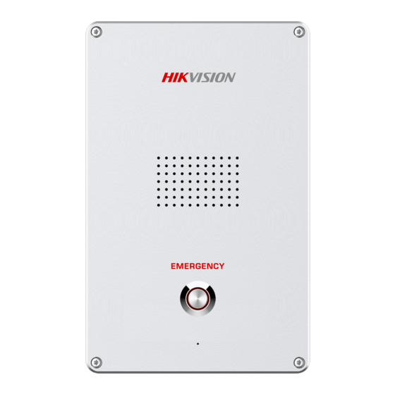
Panic Alarm Station User Manual Overview Description DS-PEA102A series of panic alarm station supports two –way audio communication, and panic alarm, which realize alarm aid in emergency. The product is applied in school, hospital, metro, scenic area, prison, etc. Key Features ... -
Page 9: Chapter 2 Activating The Control Panel
Panic Alarm Station User Manual Activating the Control Panel Purpose: You are required to activate the control panel first before you can use the control panel. Activation via SADP, and Activation via client software are supported. Activation via SADP Software SADP software is used for detecting the online device, activating the device, and resetting the password. - Page 10 Panic Alarm Station User Manual 6. Input the password and click the Modify button to activate your IP address modification. Activation via Client Software The client software is versatile video management software for multiple kinds of devices. Get the client software from the supplied disk or the official website, and install the software according to the prompts. Follow the steps to activate the control panel.
- Page 11 Panic Alarm Station User Manual Click the Device Management icon to enter the Device Management interface, as shown in the figure below. Click Add Device Type to enter the adding device type page. Select Security Control Panel. Click Security Control Panel in the Organization list. Check the device status from the device list, and select an inactive device.
- Page 12 Panic Alarm Station User Manual Change the device IP address to the same subnet with your computer by either modifying the IP address manually or checking the checkbox of Enable DHCP. Input the password to activate your IP address modification.
-
Page 13: Chapter 3 Remote Settings
Panic Alarm Station User Manual Remote Settings In the client software, go to Control Panel → Device Management, click and select the device in the Device for Management, and click Remote Configuration to go to Remote Configuration page. Note ● The device should be activated the first time it is used to log in and use properly. See Activation to activate the device. ●... -
Page 14: Edit Network Parameters
Panic Alarm Station User Manual In the client software, go to Device Management → Device on the Maintenance and Management list. You can add devices to client software by several methods on the device management page. The following describes how to add devices through IP/Domain Name. For more information, see iVMS-4200 Client Software User Manual. -
Page 15: Network Configuration
Panic Alarm Station User Manual Network Configuration Set General Network Parameters Configure network mode, IP address, NIC and NIC type, subnet mask, gateway, MAC address, MTU settings, and port No. for device. Before You Start Make sure the cable of the device is connected. Steps Note The network mode is multiple networks mode, you can set the basic network parameters for NIC 1 and NIC 2. -
Page 16: Set Dns
Panic Alarm Station User Manual Note NIC 1 and NIC 2 are independent of DHCP. – Manually set the network address According to the actual network environment, manually set the network address IPv4 Address, Subnet Mask (IPv4), Default Gateway (IPv4). 4. -
Page 17: Set Nat
Panic Alarm Station User Manual Set NAT Enable the UPnP function, and you don't need to configure the port mapping for each port, and the device is connected to the Wide Area Network via the router. Steps Note Universal Plug and Play (UPnP™) is a networking architecture that provides compatibility among networking equipment, software and other hardware devices. - Page 18 Panic Alarm Station User Manual 2. Check Enable UPnP, and set Mapping Types as Manual or Auto. – Set Mapping Types as Auto The Ports are read-only, and the external ports are set by the router automatically. – Set Mapping Types as Manual You can edit the external port on your demand.
-
Page 19: Set Sip
Panic Alarm Station User Manual Set SIP After the SIP server address is set, the device actively registers to the SIP server, and devices under the same SIP server address can communicate with each other. Steps 1. On the Remote Configuration page, go to Network → SIP Settings. 2. -
Page 20: Set Hik-Connect
Panic Alarm Station User Manual Set Hik-Connect Enable Hik-Connect service and you can add the device to Hik-Connect. Steps 1. On the Remote Configuration page, go to Network → Hik-Connect Service Settings. Figure 3-10 Hik-Connect Service Setting Page 2. Check Enable Hik-Connect Access. 3. - Page 21 Panic Alarm Station User Manual Figure 3-11 Platform Access Configuration(ISUP 2.0) 2. Check Enable Platform Access to enable the Platform Access function. 3. Set the platform access parameters. Access Type Select the platform to be accessed. Server IP or Domain Name Enter the IP address or domain name of the platform.
-
Page 22: Set Alarm Center
Panic Alarm Station User Manual Set Alarm Center Configure the alarm center. When an alarm is triggered, the alarm information can be uploaded to the configured alarm center. Steps 1. On the Remote Configuration page, go to Network → Network Center Configure. 2. -
Page 23: Alarm Settings
Panic Alarm Station User Manual Port The port number of the upload center. The HIK protocol defaults to 7200; the NAL2300 protocol needs to be set to 4001. Protocol Type The default is HIK. Can be set to HIK or NAL2300. User Name Supports numbers and letters. - Page 24 Panic Alarm Station User Manual 3. Select an zone, click...
- Page 25 Panic Alarm Station User Manual 4. Set zone parameters. Name Zone name. Detector Type The detector type of the zone. Zone Type Four zone type can be set for Non-default zones: Instant Zone, Fire Zone, 24-hour Non-voiced Zone, Shield Zone. Instant Zone In the armed state, as long as the detector connected to the zone is triggered, an alarm is generated immediately without delay.
-
Page 26: Set Relay
Panic Alarm Station User Manual Upload Alarm Recovery Report If check Upload Alarm Recovery Report, the report will be uploaded to the center when the alarm is restored. 5. Select the zone linkage. Linked Trigger After the zone is triggered, the selected alarm output is on. Channel After the zone is triggered, the selected video channel is linked. - Page 27 Panic Alarm Station User Manual Name The relay name. Output Delay(s) The output delay time, can be set from 0 to 2000s. After the zone event is triggered, the relay will turn off the relay output after the output delay time is ended. 3.
-
Page 28: Set Call Waiting
Panic Alarm Station User Manual Set Call Waiting Configure the call waiting parameters, include the maximum ring duration and waiting time. Steps 1. On the Remote Configuration page, go to Output Settings → Waiting. 2. Set the call waiting parameters. Max. -
Page 29: Alarm Management
Panic Alarm Station User Manual 2. Set the Center Busy File, Refuse Prompt, Voice Talk Ending Prompt, Emergency Help Prompt, and Consultant Help Prompt. 3. Optional: Configure the mute program. 1) Check Enable to enable the mute program. 2) Click and drag the mouse on the time bar to draw the scheduled time period. 3) Optional: Edit the time period. -
Page 30: Manage Audio Input/Output
Panic Alarm Station User Manual Check the relays that need to be turned on/off. Click Open/Close to change the relay switch status. Click Refresh, you can refresh the relay switch status. Manage Audio Input/Output Configure the audio input/audio output mode and the volume of the corresponding mode. Steps 1. -
Page 31: Video & Audio Settings
Panic Alarm Station User Manual 2. Set the audio input/output mode and volume. Note ● spkOut is the device's own audio input/output. lineOut1 are 3.5mm hole interfaces, which can connect to the external microphones and speakers. 3. Click Save. Video & Audio Settings Video &... - Page 32 Panic Alarm Station User Manual Select a camera, and set the video and audio parameters. Click Save to save the settings. Note ● You can click Copy to... to copy the parameters to other camera. ● After editing the video and audio parameters, the device won't reboot. ●...
-
Page 33: Set Display
Panic Alarm Station User Manual Resolution According to the requirements for video clarity, the higher the resolution, the higher the bandwidth requirement for the network. Frame Rate Video frames per second. According to the actual bandwidth setting, the higher the video frame rate, the higher the required bandwidth and the higher the required storage space. - Page 34 Panic Alarm Station User Manual Select a camera from the drop-down box to configure the display parameters of the camera, including display position, display format and optional display content, you are able to add custom display information. Editing the display position Drag the blue box on the live view page to change the position of the display information, click Save, and then the position of the display information will be updated.
-
Page 35: Set Intercom Audio
Panic Alarm Station User Manual Click Save to save the settings. ● Editing the camera name Editing the camera name in the Camera Name text box and click Save. ● Adding custom display content Click the right area of the check box in the Text Overlay List and enter display content in the text box. Check the text and click Save to display the custom information. -
Page 36: System Settings
Panic Alarm Station User Manual System Settings Set Time On the Remote Configuration page, go to Device Information → Time. You can set the time zone, NTP, DST on the Time page. You can also click Synchronization to implement SDK synchronization. Set System Parameters Set the device name, device No. -
Page 37: Set Security
Panic Alarm Station User Manual Set the device name and device No., and select Yes or No from the Overwrite Record Files drop-down box. Click Save to save the settings. Note Select Overwrite Record Files as Yes, the new video file will overwrite the earliest video file when the device storage is full. Set Security Enable/disable SSH service, which is used to provide security configuration for remote debugging. -
Page 38: Set Password
Panic Alarm Station User Manual Check Enable SSH to enable SSH service, and click Save. Note By default, the SSH service is not enabled. The default setting will be restored after the restart. Set Password Set the maximum password attempts, the lock duration of the locked user. And you can unlock the user remotely. Steps 1. - Page 39 Panic Alarm Station User Manual IP Address The IP address of the terminal in which the locked user logs. Unlock The user's access lock status on the corresponding IP address. 2. Enable the access lock function and set the lock parameters. 1) Check Access Lock to enable the access lock function.
-
Page 40: Set User
Panic Alarm Station User Manual Set User Steps Note The device only has the admin user and only supports modifying the admin user password. 1. On the Romte Configuration page, go to System → User. 2. Edit the admin user password. 1) Select the admin user and click Edit. -
Page 41: Maintain The System
Panic Alarm Station User Manual Note You can click Backup and download the search result. Maintain the System System management and remote upgrade. On the Remote Configuration page, go to System → System Maintenance. - Page 42 Panic Alarm Station User Manual System Management You can reboot the device, restore default settings, restore all settings, and import/export configuration file. Reboot Restart the device. Restore Default Settings Restore the default settings, that is, except the IP address and user information, all other parameters of the device will be restored to factory default settings.
-
Page 43: View Device Information
Panic Alarm Station User Manual Note The configuration file contains the parameter information of the device. It is required to set a password for the exported file. The password is used for importing verification. Remote Upgrade Upgrade the device remotely via the client software. Click and select the upgrading file. -
Page 44: Check Status
Panic Alarm Station User Manual Check Status Check Zone Status On the Remote Configuration page, go to Status → Zone, you can view the status of zone alarm. Check Relay Status On the Remote Configuration page, go to Status → Relay, you can view the relay status. - Page 45 Panic Alarm Station User Manual...
Need help?
Do you have a question about the DS-PEA102S and is the answer not in the manual?
Questions and answers