Table of Contents
Advertisement
Quick Links
Advertisement
Table of Contents

Related Manuals for HIKVISION DS-PEA Series


Summary of Contents for HIKVISION DS-PEA Series
- Page 1 Panic Alarm Station Configuration Guide...
- Page 2 INTERRUPTION, OR LOSS OF DATA, CORRUPTION OF SYSTEMS, OR LOSS OF DOCUMENTATION, WHETHER BASED ON BREACH OF CONTRACT, TORT (INCLUDING NEGLIGENCE), PRODUCT LIABILITY, OR OTHERWISE, IN CONNECTION WITH THE USE OF THE PRODUCT, EVEN IF HIKVISION HAS BEEN ADVISED OF THE POSSIBILITY OF SUCH DAMAGES OR LOSS.
- Page 3 Panic Alarm Station Configuration Guide PRODUCTION OF CHEMICAL OR BIOLOGICAL WEAPONS, ANY ACTIVITIES IN THE CONTEXT RELATED TO ANY NUCLEAR EXPLOSIVE OR UNSAFE NUCLEAR FUEL-CYCLE, OR IN SUPPORT OF HUMAN RIGHTS ABUSES. IN THE EVENT OF ANY CONFLICTS BETWEEN THIS MANUAL AND THE APPLICABLE LAW, THE LATER PREVAILS.
- Page 4 Panic Alarm Station Configuration Guide Symbol Conventions The symbols that may be found in this document are defined as follows. Symbol Description Indicates a hazardous situation which, if not avoided, will or could Danger result in death or serious injury. Indicates a potentially hazardous situation which, if not avoided, Caution could result in equipment damage, data loss, performance...
- Page 5 Panic Alarm Station Configuration Guide Regulatory Information FCC Information Please take attention that changes or modification not expressly approved by the party responsible for compliance could void the user’s authority to operate the equipment. FCC compliance: This equipment has been tested and found to comply with the limits for a Class B digital device, pursuant to part 15 of the FCC Rules.
-
Page 6: Table Of Contents
Panic Alarm Station Configuration Guide Contents Chapter 1 Overview........................1 Chapter 2 Activation........................2 2.1 Activate via SADP ........................2 2.2 Activate Device via Client Software ..................3 Chapter 3 Remote Settings ......................5 3.1 Device Management ......................5 3.1.1 Add Device to the Client Software ................5 3.1.2 Edit Network Parameters ................... - Page 7 Panic Alarm Station Configuration Guide 3.4.4 Manage Strobe Light ....................25 3.4.5 Manage Audio File....................25 3.4.6 Manage Strobe Light Flicking ................... 27 3.5 Event Settings ........................28 3.5.1 Schedule Settings ..................... 28 3.5.2 Set Audio Exception Detection ................34 3.6 Video &...
- Page 8 Panic Alarm Station Configuration Guide 3.10.2 Check Relay Status ....................52...
-
Page 9: Chapter 1 Overview
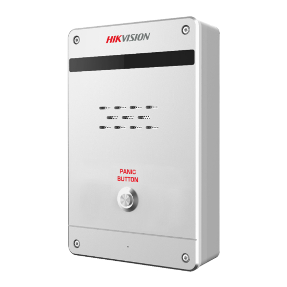
Chapter 1 Overview Description DS-PEA series of active panic alarm station supports dual network ports. It provides200W high- definition camera, center call, strobe light work schedule, two-way audio, remote/local open electric lock, external network camera to increase field of view and other functions. The device supports video call with the center, and linkage with the surrounding cameras and external lamp, sound box, etc. -
Page 10: Chapter 2 Activation
Before You Start ● Get the SADP software from the supplied disk or the official website http://www.hikvision.com/en/, and install the SADP according to the prompts. ● The device and the PC that runs the SADP tool should be within the same subnet. -
Page 11: Activate Device Via Client Software
Before You Start ● Get the iVMS-4200 client software from the supplied disk or the official website http://www.hikvision.com/en/. Install the software by following the prompts. ● Get the Guarding Vision client software from the supplied disk. Install the software by following the prompts. - Page 12 Panic Alarm Station Configuration Guide Caution STRONG PASSWORD RECOMMENDED-We highly recommend you create a strong password of your own choosing (using a minimum of 8 characters, including upper case letters, lower case letters, numbers, and special characters) in order to increase the security of your product. And we recommend you reset your password regularly, especially in the high security system, resetting the password monthly or weekly can better protect your product.
-
Page 13: Chapter 3 Remote Settings
Panic Alarm Station Configuration Guide Chapter 3 Remote Settings In the client software, go to Control Panel → Device Mnagement, click and select the device in the Device for Management, and click Remote Configuration to go to Remote Configuration page. Note ●... -
Page 14: Edit Network Parameters
Panic Alarm Station Configuration Guide management page. The following describes how to add devices through IP/Domain Name. For more information, see iVMS-4200 Client Software User Manual. Steps 1. On the Device page, click Add. 2. Select IP/Domain as the adding mode, edit the device information, including Name, Address, Port, User Name, and Password. - Page 15 Panic Alarm Station Configuration Guide Steps Note The network mode is multiple networks mode, you can set the basic network parameters for NIC 1 and NIC 2. 1. On the Remote Configuration page, go to Network → General. Figure 3-2 Network Basic Settings Page 2.
-
Page 16: Set Dns
Panic Alarm Station Configuration Guide Device Port The default device port number is 8000. HTTP port The default port number is 80, and it can be changed to any port No. which is not occupied. RTSP port The default port number is 554 and it can be changed to any port No. ranges from 1 to 65535. Default NIC The default NIC is NIC 1 and it can be set to NIC 1 or NIC 2. - Page 17 Panic Alarm Station Configuration Guide Figure 3-4 NAT Setting Page 2. Check Enable UPnP, and set Mapping Types as Manual or Auto. – Set Mapping Types as Auto The Ports are read-only, and the external ports are set by the router automatically. –...
-
Page 18: Set Alarm Center
Panic Alarm Station Configuration Guide 3.2.4 Set Alarm Center Configure the alarm center. When an alarm is triggered, the alarm information can be uploaded to the configured alarm center. Steps 1. On the Remote Configuration page, go to Network → Network Center Configure. Figure 3-5 Alarm Center Configuration 2. -
Page 19: Set Sip
Panic Alarm Station Configuration Guide User Name Supports numbers and letters. The HIK protocol can be set to a length ranging from 6 to 9 digits; the NAL2300 protocol can be set to a length of 6 digits. Note If you set the protocol type as HIK, you do not need to edit the user name. 4. -
Page 20: Data Limit
Panic Alarm Station Configuration Guide Port The SIP server port. By default, the private SIP port is 5065 and the standard SIP port is 5060. The available server port number should be between 1024 and 65535. Local Listening Port The local port of the device SIP function. By default, the local listening port is 5060. The available port number should be between 1024 and 65535. -
Page 21: Set Wireless Dialing
Panic Alarm Station Configuration Guide message prompt. Steps Note ● The data traffic will be calculated form the first day per month. ● The message prompt should be enabled, please see Set Wireless Dialing to enable the function. 1. On the Remote Configuration page, go to Network → Data Limit. Figure 3-8 Data Limit Configuration Page 2. - Page 22 Panic Alarm Station Configuration Guide Figure 3-9 Data Limit 2. Click 4G and check Enable Wireless Dial to enable the wireless dial. 3. Set the Access Number, User Name, Password, APN and MTU. Note You can also leave these parameters blank, and the device will adopt the default settings for dialing after other parameters are configured.
-
Page 23: Set Hik-Connect
Panic Alarm Station Configuration Guide 3.2.8 Set Hik-Connect Enable Hik-Connect service and you can add the device to Hik-Connect. Steps 1. On the Remote Configuration page, go to Network → Hik-Connect Service Settings. Figure 3-10 Hik-Connect Service Setting Page 2. Check Enable Hik-Connect Access and enter the verification code to enable Hik-Connect service. 3. -
Page 24: Access The Platform
Panic Alarm Station Configuration Guide 3.2.9 Access the Platform Platform access provides you an option to manage the devices via platform. Steps 1. On the Remote Configuration page, go to Network → Platform Access. Figure 3-11 Platform Access Configuration 2. Check Enable Platform Access to enable the Platform Access function. 3. -
Page 25: 11Set Intercom Parameters
Panic Alarm Station Configuration Guide Figure 3-12 Set Call Center Parameters 2. Check to enable the function 3. Set call center parameters including center type, center name, phone number, dialing times, communication protocol, transfer mode, and receiver ID. 3. Click Save. 3.2.11Set Intercom Parameters Steps 1. -
Page 26: Alarm Settings
Panic Alarm Station Configuration Guide 3.3 Alarm Settings 3.3.1 Set Zone The device supports four alarm input zones and two default zones (emergency call help and consulting). You need to configure zone parameters. Steps Note The default zone has a default zone type, default audio file, and the default zone will automatically upload an alarm recovery report. - Page 27 Panic Alarm Station Configuration Guide Figure 3-14 Set Zone Parameters 4. Set zone parameters. Name Zone name. Detector Type The detector type of the zone. Zone Type Four zone type can be set for Non-default zones: Instant Zone, Fire Zone, 24-hour Non-voiced Zone, Shield Zone.
-
Page 28: Set Relay
Panic Alarm Station Configuration Guide The default value is 500 ms. Audio File Select an audio file for zone. Upload Alarm Recovery Report If check Upload Alarm Recovery Report, the report will be uploaded to the center when the alarm is restored. 5. -
Page 29: Set Call Waiting
Panic Alarm Station Configuration Guide Figure 3-15 Relay Configuration Page Name The relay name. Output Delay(s) The output delay time, can be set from 0 to 2000s. After the zone event is triggered, the relay will turn off the relay output after the output delay time is ended. 3. -
Page 30: Set Voice Prompt
Panic Alarm Station Configuration Guide Max. Ring Duration The playback time of the calling tone when calling, can be set from 40 s to 80 s. Waiting Time The extended playback time of the prompt tone based on the maximum ring time when calling the master station and pressing the call waiting button, can b set from 10 seconds to 60 s. -
Page 31: Alarm Management
Panic Alarm Station Configuration Guide 3) Optional: Edit the time period. ● Modify the time period Click and select the added time period, drag to modify the time period position; click and select the added time period, then moves the cursor to both ends of the time period, when the cursor becomes a double arrow, you can drag the mouse left and right to modify the time period. -
Page 32: Manage Siren
Panic Alarm Station Configuration Guide Figure 3-19 Alarm Input/Output Configuration Page 2. Set the audio input/output mode and volume. Note ● spkOut is the device's own audio input/output. lineOut1 are 3.5mm hole interfaces, which can connect to the external microphones and speakers. The device defaults to micIn and spkOut. -
Page 33: Manage Strobe Light
Panic Alarm Station Configuration Guide Figure 3-20 Siren Management Page 2. Select a siren and enable Status to open the siren, or disable Status to close the siren. 3. Optional: Click Refresh to refresh the siren status. 3.4.4 Manage Strobe Light Open/Close the strobe lamp via the client software. - Page 34 Panic Alarm Station Configuration Guide Figure 3-22 Audio File Management 2. Upload the custom audio files. 1) Click Browse to select the audio file (can be selected in batch). 2) Check the audio file in the Upload File list and click Upload. Note ●...
-
Page 35: Manage Strobe Light Flicking
Panic Alarm Station Configuration Guide 3.4.6 Manage Strobe Light Flicking Enable the strobe light flicking, and you can configure the strobe light flicking schedule. Steps 1. On the Remote Configuration page, go to Alarm Management → Alarm Lamp Flicking. 2. You can enable the strobe light flicking or configure the schedule. –... -
Page 36: Event Settings
Panic Alarm Station Configuration Guide Figure 3-25 Strobe Light Flicking Schedule Note You can delete the drawn time period. ● Select a time period, and click Delete to delete it. ● Click Empty to delete all time period. 3. Click Save. 3.5 Event Settings 3.5.1 Schedule Settings Configure the recording and capture schedule. - Page 37 Panic Alarm Station Configuration Guide Figure 3-26 Schedule Configuration Page Select a camera, and configure the record and capture schedule. Click Save to save the settings. Note The panic alarm station without camera does not support capture schedule configuration. Record schedule configuration Local Recording Check Local Recording to enable the recording.
- Page 38 Panic Alarm Station Configuration Guide Figure 3-27 Advanced Settings of Record Pre-record The pre-recording time can be selected as 5 s or not pre-record. Post-record The delay recording time can be selected as 5 s or 10 s. Record Audio The record audio can be set as Yes or No.
- Page 39 Panic Alarm Station Configuration Guide image at regular intervals according to the set interval. Resolution Select the picture resolution. By default, it is HD720p(1280×720). Picture Quality Set the picture quality. The higher the value, the better the picture quality. Interval Timed capture based on this time interval.
- Page 40 Panic Alarm Station Configuration Guide 2. Click Edit to go to the editing page. Figure 3-30 System Template Editing Page 3. Optional: Select the schedule type. – Continuous: Regardless of whether an event is triggered or not, the system records video according to the scheduled recording time period.
- Page 41 Panic Alarm Station Configuration Guide Figure 3-31 Draw a schedule time period 5. Edit the schedule time period. Modify the time Move the mouse to the time period that has been drawn. When the period cursor changes to the hand, click the drag time period to modify the time period position;...
-
Page 42: Set Audio Exception Detection
Panic Alarm Station Configuration Guide Figure 3-32 Custom Schedule Editing Page 2. Draw the schedule time period. For detailed, seeSet System Schedule. 3. Click Save. 3.5.2 Set Audio Exception Detection Audio exception detection means that when the sound in the environment is detected as sudden increase of sound intensity or sharp decrease of sound intensity, an alarm output will be triggered. -
Page 43: Video & Audio Settings
Panic Alarm Station Configuration Guide 2. According to actual needs, select and check Enable Sudden Increase of Sound Intensity, Enable Sudden Decrease of Sound Intensity. And set the parameters. Note Sensitivity(50) and Thresholds(50) can be set from 1 to 100 and default to 50. 3. - Page 44 Panic Alarm Station Configuration Guide Figure 3-34 Video & Audio Configuration Page Select a camera, and set the video and audio parameters. Click Save to save the settings. Note ● You can click Copy to... to copy the parameters to other camera. ●...
-
Page 45: Set Display
Panic Alarm Station Configuration Guide Frame Rate Video frames per second. According to the actual bandwidth setting, the higher the video frame rate, the higher the required bandwidth and the higher the required storage space. I Frame Interval The number of frames between the two key frames before and after. The larger the I frame interval is, the smaller the code stream fluctuation is, but the image quality is relatively poor. - Page 46 Panic Alarm Station Configuration Guide Figure 3-35 Video Display Configuration Page Select a camera from the drop-down box to configure the display parameters of the camera, including display position, display format and optional display content, you are able to add custom display information.
-
Page 47: Set Image Parameters
Panic Alarm Station Configuration Guide display content. ● Selecting the display content According to your requirement, check Display Camera Name, Display Date, Display Week to display the selected display content. Click Save to save the settings. ● Editing the camera name Editing the camera name in the Camera Name text box and click Save. -
Page 48: Set Intercom Audio
Panic Alarm Station Configuration Guide Click Default Value, you can restore all video parameters to default. 3.6.4 Set Intercom Audio On the Remote Configuration page, go to Image → Intercom Audio. Figure 3-37 Intercom Audio Configuration Page Select the Audio Encoding Type as G711_U, G726, AAC, or OPUS from the drop-down box. And click Save to save the settings. -
Page 49: Set System Parameters
Panic Alarm Station Configuration Guide 3.7.2 Set System Parameters Set the device name, device No. and configure the video files. On the Remote Configuration page, go to System → General Parameters. Figure 3-38 System Parameters Setting Page Set the device name and device No., and select Yes or No from the Overwrite Record Files drop- down box. - Page 50 Panic Alarm Station Configuration Guide user remotely. Steps 1. On the Remote Configuration page, go to System → Password Management. Figure 3-40 Password Management Page IP Address The IP address of the terminal in which the locked user logs. Unlock The user's access lock status on the corresponding IP address.
-
Page 51: Set User
Panic Alarm Station Configuration Guide 3) Click Save. 3. Optional: Click Unlock All to unlock all user. 3.7.5 Set User Steps Note The device only has the admin user and only supports modifying the admin user password. 1. On the Romte Configuration page, go to System → User. 2. -
Page 52: Search For Log
Panic Alarm Station Configuration Guide 3.7.6 Search for Log Search and view the alarm logs, exception logs, operation logs and event logs. On the Remote Configuration page, go to System → Log. You can set the search criteria and click Search, and the search result is in the list. Figure 3-42 Search and View the Log Note You can click Backup and download the search result. - Page 53 Panic Alarm Station Configuration Guide Figure 3-43 System Maintenance Page System Management You can reboot the device, restore default settings, restore all settings, and import/export configuration file. Reboot Restart the device. Restore Default Settings Restore the default settings, that is, except the IP address and user information, all other parameters of the device will be restored to factory default settings.
-
Page 54: Check Video & Audio Status
Panic Alarm Station Configuration Guide Remote Upgrade Upgrade the device remotely via the client software. Click and select the upgrading file. And click Upgrade to upgrade the device. Note An invalid upgrade occurs when using a mismatched upgrade file, and then the device program is still the program before the upgrade. -
Page 55: View Device Information
Panic Alarm Station Configuration Guide Everyday Check every day according to the set time. One day of the week The device performs a check at the set time on this day of the week. Manual check Click Check to start the check and the check results are displayed in the list. Table 3-1 Description of Check Results Check results Description... -
Page 56: Add Camera
Panic Alarm Station Configuration Guide and video standard. 3.8.1 Add Camera Add, modify and delete an external network camera, and enable the camera. Steps Note Only one network camera can be added to the device. 1. On the Remote Configuration page, go to System → Camera. 2. -
Page 57: Set Video Parameters
Panic Alarm Station Configuration Guide Figure 3-47 Select the Camera Number 3) Click Save 3. Optional: You can select the camera in the list, and click modify to modify the camera parameters, or click Delete to delete the added camera. 4. -
Page 58: Set Other Parameters
Panic Alarm Station Configuration Guide Figure 3-49 WDR function Configuration 2. Select a camera, set WDR Mode as On. 3. Set WDR Level. Note The WDR level can change the wide dynamic strength. 4. Click Save to enable WDR. 3.8.4 Set Other Parameters Steps 1. -
Page 59: Storage Settings
Panic Alarm Station Configuration Guide 3.9 Storage Settings 3.9.1 Initialize HHD In order to store pictures and video files, you must format the MicroSD card first. Steps 1. In the client software, go to Control Panel → Device Management, select the device in the device list, and click Remote Configuration. -
Page 60: Search For File
Panic Alarm Station Configuration Guide 3.9.2 Search for File Search and download the record file and captured picture. Steps 1. On the Remote Configuration page, go to Storage → File. 2. Select the searched file type as Record File or Captured Picture. 3. - Page 61 Panic Alarm Station Configuration Guide Chapter 4 Communication Matrix and Device Command Scan the OR code for communication matrix Scan the QR code for device command...
Need help?
Do you have a question about the DS-PEA Series and is the answer not in the manual?
Questions and answers