Table of Contents
Advertisement
Quick Links
Advertisement
Table of Contents

Subscribe to Our Youtube Channel
Related Manuals for HIKVISION DS-PEA101 Series


Summary of Contents for HIKVISION DS-PEA101 Series
- Page 1 Non-Visible Panic Alarm Station Configuration Guide...
- Page 2 INTERRUPTION, OR LOSS OF DATA, CORRUPTION OF SYSTEMS, OR LOSS OF DOCUMENTATION, WHETHER BASED ON BREACH OF CONTRACT, TORT (INCLUDING NEGLIGENCE), PRODUCT LIABILITY, OR OTHERWISE, IN CONNECTION WITH THE USE OF THE PRODUCT, EVEN IF HIKVISION HAS BEEN ADVISED OF THE POSSIBILITY OF SUCH DAMAGES OR LOSS.
- Page 3 Non-Visible Panic Alarm Station Configuration Guide PRODUCTION OF CHEMICAL OR BIOLOGICAL WEAPONS, ANY ACTIVITIES IN THE CONTEXT RELATED TO ANY NUCLEAR EXPLOSIVE OR UNSAFE NUCLEAR FUEL-CYCLE, OR IN SUPPORT OF HUMAN RIGHTS ABUSES. IN THE EVENT OF ANY CONFLICTS BETWEEN THIS MANUAL AND THE APPLICABLE LAW, THE LATER PREVAILS.
- Page 4 Non-Visible Panic Alarm Station Configuration Guide Symbol Conventions The symbols that may be found in this document are defined as follows. Symbol Description Indicates a hazardous situation which, if not avoided, will or could Danger result in death or serious injury. Indicates a potentially hazardous situation which, if not avoided, Caution could result in equipment damage, data loss, performance...
- Page 5 Non-Visible Panic Alarm Station Configuration Guide Regulatory Information FCC Information Please take attention that changes or modification not expressly approved by the party responsible for compliance could void the user’s authority to operate the equipment. FCC compliance: This equipment has been tested and found to comply with the limits for a Class B digital device, pursuant to part 15 of the FCC Rules.
-
Page 6: Table Of Contents
Non-Visible Panic Alarm Station Configuration Guide Contents Chapter 1 Overview........................1 Chapter 2 Activation........................2 2.1 Activate via SADP ........................2 2.2 Activate Device via Client Software ..................3 Chapter 3 Remote Settings ......................5 3.1 Device Management ......................5 3.1.1 Add Device to the Client Software ................ - Page 7 Non-Visible Panic Alarm Station Configuration Guide 3.5.1 Set Audio Exception Detection ................26 3.6 Video & Audio Settings ....................... 28 3.6.1 Video & Audio Settings .................... 28 3.6.2 Set Display ........................ 30 3.6.3 Set Image Parameters ....................31 3.6.4 Set Intercom Audio ....................31 3.7 System Settings ........................
-
Page 8: Chapter 1 Overview
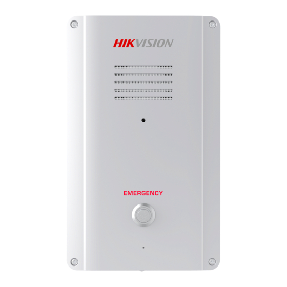
Chapter 1 Overview Description DS-PEA101 series of active panic alarm station has 1-channel alarm input and 1-channel alarm output. It supports center call, two-way video intercom, real-time monitoring, first time alarm help and audio anomaly detection. It can provide faster and more effective services for the society, effectively deter criminals, reassure the public, and stabilize the society. -
Page 9: Chapter 2 Activation
Before You Start ● Get the SADP software from the supplied disk or the official website http://www.hikvision.com/en/, and install the SADP according to the prompts. ● The device and the PC that runs the SADP tool should be within the same subnet. -
Page 10: Activate Device Via Client Software
Before You Start ● Get the iVMS-4200 client software from the supplied disk or the official website http://www.hikvision.com/en/. Install the software by following the prompts. ● Get the Guarding Vision client software from the supplied disk. Install the software by following the prompts. - Page 11 Non-Visible Panic Alarm Station Configuration Guide 2) Change the device IP address to the same subnet with your computer and set port number as 3) Enter the admin password of the device and click OK to complete modification. 10. Optional: Check the device on the online device list and click Add to add the device to the device list.
-
Page 12: Chapter 3 Remote Settings
Non-Visible Panic Alarm Station Configuration Guide Chapter 3 Remote Settings In the client software, go to Device Management, click and select the device in the device list, and click to go to Remote Configuration page. Note ● The device should be activated the first time it is used to log in and use properly. See Activation to activate the device. -
Page 13: Edit Network Parameters
Non-Visible Panic Alarm Station Configuration Guide more information, see iVMS-4200 Client Software User Manual. Steps 1. On the Device page, click Add. 2. Select IP/Domain as the adding mode, edit the device information, including Name, Address, Port, User Name, and Password. Note The port No. - Page 14 Non-Visible Panic Alarm Station Configuration Guide Steps Note The network mode is multiple networks mode, you can set the basic network parameters for NIC 1 and NIC 2. 1. Click to enter the Remote Configuration page, go to Network → General. Figure 3-2 Network Basic Settings Page 2.
-
Page 15: Set Dns
Non-Visible Panic Alarm Station Configuration Guide Maximum transmission unit, which refers to the maximum packet size passed by TCP/UDP protocol network transmission. The default is 1500. Device Port The default device port number is 8000. HTTP port The default port number is 80, and it can be changed to any port No. which is not occupied. RTSP port The default port number is 554 and it can be changed to any port No. - Page 16 Non-Visible Panic Alarm Station Configuration Guide the device is connected to the Wide Area Network via the router. Steps Note Universal Plug and Play (UPnP™) is a networking architecture that provides compatibility among networking equipment, software and other hardware devices. The UPnP protocol allows devices to connect seamlessly and to simplify the implementation of networks in the home and corporate environments.
-
Page 17: Set Alarm Center
Non-Visible Panic Alarm Station Configuration Guide the modified port number to the address when you log in using the browser. For example, when the HTTP port number is changed to 81, you need to enter http://192.168.1.64:81 when you log in using a browser. Server Port By default, the value of the Server port No. -
Page 18: Set Sip
Non-Visible Panic Alarm Station Configuration Guide Notify Surveillance Center Each NIC supports only one upload center, and the default is Net Center 1. Server Mode The address type of the upload center server. You can set Server Type as IP4/IP6 or Domain Name. - Page 19 Non-Visible Panic Alarm Station Configuration Guide Figure 3-7 SIP Setting Page (SIP Protocol) Figure 3-6 SIP Setting Page (Private Protocol) Registration Status Display the status of the device registers to the SIP server. 2. Select the Server as IP Address or Domain Name. 3.
-
Page 20: Set Hik-Connect
Non-Visible Panic Alarm Station Configuration Guide The interval that the device continuously registers to the SIP server, the register period ranges from 1 to 30 (min). Network Type Select the Network Type as Wired Network 1, Wired Network 2 or Wireless Network. Note When you select a wired network, the wired network is used regardless of whether the wired network is normal;... -
Page 21: Access The Platform
Non-Visible Panic Alarm Station Configuration Guide Figure 3-11 Hik-Connect Service Setting Page 2. Check Enable Hik-Connect Access to enable Hik-Connect service. 3. Optional: If you want to edit Server Address, check Custom and enter the server address. Note The default server address is litedev.hik-connect.com. 4. -
Page 22: Set Intercom Parameters
Non-Visible Panic Alarm Station Configuration Guide Figure 3-12 Platform Access Configuration 2. Check Enable to enable the Platform Access function. 3. Set the platform access parameters. Access Type Select the platform to be accessed. Server IP or Domain Name Enter the IP address or domain name of the platform. Access to Server Port Enter the port number of the platform. -
Page 23: Set Integrate Protocol Parameters
Non-Visible Panic Alarm Station Configuration Guide Figure 3-13 Intercom Parameters Configuration 2. Select the Protocol as SIP Protocol or Private Protocol. 3. Click Save. The device will reboot automatically after switching the protocol successfully. 3.2.9 Set Integrate Protocol Parameters If you need to access to the device through ONVIF protocol, you can configure the ONVIF user to enhance the network security. -
Page 24: Alarm Settings
Non-Visible Panic Alarm Station Configuration Guide 5. Click Save. 3.3 Alarm Settings 3.3.1 Set Zone The device supports four alarm input zones and two default zones (emergency call help and consulting). You need to configure zone parameters. Steps Note The default zone has a default zone type, default audio file, and the default zone will automatically upload an alarm recovery report. - Page 25 Non-Visible Panic Alarm Station Configuration Guide Figure 3-17 Set Zone Parameters 4. Set zone parameters. Name Zone name. Detector Type The detector type of the zone. Zone Type Four zone type can be set for Non-default zones: Instant Zone, Fire Zone, 24-hour Non-voiced Zone, Shield Zone.
-
Page 26: Set Relay
Non-Visible Panic Alarm Station Configuration Guide Sensitivity The default value is 500 ms. Audio File Select an audio file for zone. Upload Alarm Recovery Report If check Upload Alarm Recovery Report, the report will be uploaded to the center when the alarm is restored. -
Page 27: Set Call Waiting
Non-Visible Panic Alarm Station Configuration Guide Figure 3-18 Relay Configuration Page Name The relay name. Output Delay(s) The output delay time, can be set from 0 to 2000s. After the zone event is triggered, the relay will turn off the relay output after the output delay time is ended. 3. -
Page 28: Set Voice Prompt
Non-Visible Panic Alarm Station Configuration Guide Figure 3-19 Call Waiting Settings Page 2. Set the call waiting parameters. Calling Duration The playback time of the calling tone when calling, can be set from 40 s to 80 s. Waiting Time The extended playback time of the prompt tone based on the maximum ring time when calling the master station and pressing the call waiting button, can be set from 10 seconds to 60 s. - Page 29 Non-Visible Panic Alarm Station Configuration Guide Figure 3-20 Voice Prompt Configuration Page 2. Set the Center Busy File, Refuse Prompt, Voice Talk Ending Prompt and Panic Alarm Prompt Sound. 3. Optional: Configure the mute program. 1) Check Enable to enable the mute program. 2) Click and drag the mouse on the time bar to draw the scheduled time period.
-
Page 30: Alarm Management
Non-Visible Panic Alarm Station Configuration Guide 3.4 Alarm Management 3.4.1 Manage Relay Open or close the relay via client software. Click to enter the Remote Configuration page, go to Alarm Management → Relay Figure 3-21 Relay Management Page Check the relays that need to be turned on/off. Click Enable/Locked to change the relay switch status. -
Page 31: Manage Siren
Non-Visible Panic Alarm Station Configuration Guide Figure 3-22 Alarm Input/Output Configuration Page 2. Set the audio input/output mode and volume. Note ● micIn/ spkOut is the device's own audio input/output. lineOut1 is a 3.5mm hole interface, which can connect to the external microphones and speakers. The device defaults to micIn and spkOut. -
Page 32: Manage Audio File
Non-Visible Panic Alarm Station Configuration Guide Figure 3-23 Siren Management Page 2. Select a siren and enable Status to open the siren, or disable Status to close the siren. 3. Optional: Click Refresh to refresh the siren status. 3.4.4 Manage Audio File Upload the custom audio files to SD card, and delete the audio file in the SD card. -
Page 33: Event Settings
Non-Visible Panic Alarm Station Configuration Guide Note ● Supported Audio file format: .mp3 and .wav (16 kHz, 16 bit mono). The file name can't contain spaces at the beginning and end. The length of the file name should be not more than 31, and the file name can not contain symbols: ?\/*”<>|. - Page 34 Non-Visible Panic Alarm Station Configuration Guide Figure 3-31 Audio Exception Detection Configuration Page 2. According to actual needs, select and check Enable Sudden Increase of Sound Intensity, Enable Sudden Decrease of Sound Intensity. And set the parameters. Note Sensitivity(50) and Sound Intensity Thresholds(50) can be set from 1 to 100 and default to 50. 3.
-
Page 35: Video & Audio Settings
Non-Visible Panic Alarm Station Configuration Guide enabled detection items, and the selected alarm output signal is linked when the audio exception is detected. 3.6 Video & Audio Settings 3.6.1 Video & Audio Settings Configure the image quality, resolution and other parameters of the camera. Click to enter the Remote Configuration page, click Image →... - Page 36 Non-Visible Panic Alarm Station Configuration Guide video contains sound and images. If you don't need sound, choose Video Stream. Bitrate Type The bitrate type can be set as Constant or Variable. By default, it is Constant, where you should select a constant value from the Bitrate drop-down box. You are supposed to select the maximum bitrate when the bitrate type is set as Variable.
-
Page 37: Set Display
Non-Visible Panic Alarm Station Configuration Guide ● Please combine the actual demand and storage capacity to configure the video and audio parameters. 3.6.2 Set Display Edit the display information of the camera. Click to enter the Remote Configuration page, go to Image → View Scale. Figure 3-33 View Scale Configuration Page Select a camera from the drop-down box to configure the display parameters of the camera, including display position, display format and optional display content, you are able to add custom... -
Page 38: Set Image Parameters
Non-Visible Panic Alarm Station Configuration Guide Editing the display content You are able to select the display content optionally, edit the camera name, and add the custom display content. ● Selecting the display content According to your requirement, check Display Name, Display Date, Display Week to display the selected display content. -
Page 39: System Settings
Non-Visible Panic Alarm Station Configuration Guide Figure 3-35 Intercom Audio Configuration Page Select the Audio Encoding Type as G711_U, PCM, ADPCM, AAC, or OPUS from the drop-down box. And click Save to save the settings. Note EZVIZ intercom only supports G711_U and AAC. 3.7 System Settings 3.7.1 Set Time Click... -
Page 40: Set System Parameters
Non-Visible Panic Alarm Station Configuration Guide You can set the time zone, NTP, DST on the Time page. You can also click Synchronization to implement SDK synchronization. 3.7.2 Set System Parameters Set the device name, device No. and configure the video files. Click to enter the Remote Configuration page, go to System →... -
Page 41: Set Password
Non-Visible Panic Alarm Station Configuration Guide 3.7.4 Set Password Set the maximum password attempts, the lock duration of the locked user. And you can unlock the user remotely. Steps 1. Click to enter the Remote Configuration page, go to System → Password Management. Figure 3-39 Password Management Page IP Address The IP address of the terminal in which the locked user logs. -
Page 42: Set User
Non-Visible Panic Alarm Station Configuration Guide 3.7.5 Set User Steps Note The device only has the admin user and only supports modifying the admin user password. 1. Click to enter the Remote Configuration page, go to System → User. 2. Edit the admin user password. 1) Select the admin user and click Edit. -
Page 43: Maintain The System
Non-Visible Panic Alarm Station Configuration Guide Figure 3-41 Search and View the Log Note You can click Backup and download the search result. 3.7.7 Maintain the System System management and remote upgrade. Click to enter the Remote Configuration page, go to System → System Maintenance. - Page 44 Non-Visible Panic Alarm Station Configuration Guide Figure 3-42 System Maintenance Page System Management You can reboot the device, restore default settings, restore all settings, and import/export configuration file. Reboot Restart the device. Restore Default Settings Restore the default settings, that is, except the IP address, all other parameters of the device will be restored to factory default settings.
-
Page 45: Check Video & Audio Status
Non-Visible Panic Alarm Station Configuration Guide Remote Upgrade Upgrade the device remotely via the client software. Click and select the upgrading file. And click Upgrade to upgrade the device. Note An invalid upgrade occurs when using a mismatched upgrade file, and then the device program is still the program before the upgrade. -
Page 46: Security Audit Log
Non-Visible Panic Alarm Station Configuration Guide Everyday Check every day according to the set time. One day of the week The device performs a check at the set time on this day of the week. Manual check Click Verity to start the check and the check results are displayed in the list. Table 3-1 Description of Check Results Check results Description... -
Page 47: Check Status
Non-Visible Panic Alarm Station Configuration Guide 2. Set log server IP and server port. 3. Click … to upload the CA certificate. 4. Click Save. 3.8 Check Status 3.8.1 Check Zone Status Click to enter the Remote Configuration page, go to Status → Zone, you can view the status of zone alarm. - Page 48 Non-Visible Panic Alarm Station Configuration Guide Scan the QR code to get the device command.
- Page 49 UD24610B...
Need help?
Do you have a question about the DS-PEA101 Series and is the answer not in the manual?
Questions and answers