Table of Contents
Advertisement
Quick Links
Advertisement
Table of Contents

Related Manuals for Baur PD-TaD 62

Summary of Contents for Baur PD-TaD 62
- Page 1 User manual Portable PD diagnostics system PD-TaD 62 The figure is illustrative ▪ ▪ B A U R G m b H R a i f f e i s e n s t r . 6 8 3 2...
- Page 2 BAUR GmbH, 6832 Sulz, Austria. We reserve the right in the interests of our customers to make amendments as a result of further technical development.
-
Page 3: Table Of Contents
Calibrator ................21 3.6.2 Connection cables..............22 Mounting bracket ................24 Power supply ..................24 Markings on the PD-TaD 62 .............. 25 Technical data .................... 26 Operating the PD-TaD 62 ................27 Switching on the system ..............27 5.1.1 Operating states ..............27 Switching off the system following faults or in emergencies.... - Page 4 6.11.3 Connecting the system using an HV connection cable with operational earthing (option) ......... 51 6.12 Connecting the HF filter to the PD-TaD 62 ........55 6.12.1 Connection without a connection piece ....... 55 6.12.2 Connection with a connection piece ........56 6.12.3 Connection with an HV connection cable with MC plug ..
- Page 5 Repeating a measurement at a later point in time ......... 98 Maintenance ....................99 18.1 Special maintenance instructions ............99 18.2 Cleaning the PD-TaD 62 and system components ......99 18.3 Replacing the device protection fuses in the Power Box....100 18.4 Replacing the calibrator battery ............101 18.5 Accessories and spare parts ............
- Page 6 Table of contents PD-TaD 62 20.2 Storage .................... 104 Warranty and After Sales ................ 104 Disposal ....................105 Delivery scope and options ..............105 Declaration of conformity ............... 106 Glossary ....................107 Index......................110 vi / 114 822-187-3...
-
Page 7: About This Manual
Read this user manual completely before operating the product for the first time. Consider this user manual to be a part of the product and store it in an easily accessible location. If this user manual is lost, please contact BAUR GmbH or your nearest BAUR representative (http://www.baur.eu/baur-worldwide). Applicable documents This user manual applies in conjunction with the following documents: ... -
Page 8: View Settings
About this manual PD-TaD 62 Danger levels Signal words in the safety instructions specify the danger levels. DANGER Will lead to severe injuries or death. WARNING May lead to severe injuries or death. CAUTION May lead to light to moderate injuries. -
Page 9: Note On The Screenshots And Graphics Used
PD-TaD 62 About this manual Note on the screenshots and graphics used The screenshots and graphics used are intended to illustrate the procedure and may differ slightly from the actual state. 822-187-3 9 / 114... -
Page 10: For Your Safety
PD-TaD 62 OR YOUR SAFETY All BAUR devices and systems are manufactured according to the state of the art and are safe to operate. The individual parts and the finished devices are subject to continuous testing by our qualified personnel as part of our quality assurance system. Each device and system is tested before delivery. -
Page 11: Instructions For The Operator
Operate the system only in a technical perfect condition. Only use the PD-TaD 62 for the intended VLF HV generators specified on the data sheet. Connecting the PD-TaD 62 to VLF HV generators with a higher output voltage can lead to flashovers. -
Page 12: Dangers When Working With High Voltage
2.3.1 Dangers when working with high voltage During tests and measurements with the PD-TaD 62, dangerous - at times very high - voltage is generated that is fed to the test object via an HV connection cable. Personnel need to pay special attention and must be very careful while working with high electric voltage. - Page 13 PD-TaD 62 For your safety Observe 5 safety rules Comply with the following safety rules before beginning tasks in and on the electrical plant: 1. Disconnect the test object. 2. Secure against re-connection. 3. Verify absence of operating voltage.
-
Page 14: Guaranteeing Immediate Measures In An Emergency
Special personal protective equipment Personal protective equipment based on the risk assessment for the relevant working conditions is part of the PD-TaD 62 safety concept. Observe the national safety regulations and your company's working and operating instructions. -
Page 15: Product Information
PD-TaD 62 Product information RODUCT INFORM ATION Available methods Measurements using the following methods are possible with the PD-TaD 62: Method Description Required VLF HV generator Partial discharge Is used to identify and locate PD activities in the cable frida / viola... -
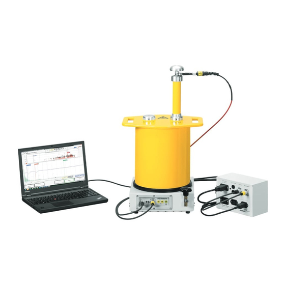
Page 16: Full Illustration Of The Pd-Tad And System Components
Element Function Laptop The laptop with the BAUR software 4 installed on it forms the graphical interface for controlling the PD diagnostics system and evaluating the measurement results. The measurement results are displayed, analysed and archived in the BAUR Software. -
Page 17: Pd-Tad
PD-TaD 62 Product information PD-TaD Designation Element Function on device – PD measuring unit Is used for the measurement and location of partial discharges Protective earthing Is used to connect the protective earthing connection The earthing connection for the short circuit cable is located on the side of the protective earthing connection. -
Page 18: Power Box
Product information PD-TaD 62 Designation Element Function on device Power Box Port Is used to connect the PD-TaD to the Power Box using a PoE cable (for power supply and data transmission) Ports Are used to connect the VSE cable for the dissipation... -
Page 19: Hf Filter
Is used to connect the PD measuring unit of the PD-TaD 62 The PD measurement unit is connected to the Power Box via a PoE cable. The PoE cable is used for the power supply of the PD-TaD 62 and for data transmission. -
Page 20: Connection Set In Transport Case
Used to protect against corona discharges anti-corona protection device HV connection cables, Are used to connect the PD-TaD 62 to the test object length 0.7 m and 1.2 m Calibrator CAL1B/CAL1E Is used to calibrate the PD test circuit Power Box Is used for: ... -
Page 21: Calibrator
Cable length or speed of the PD pulses. The delivered calibrator is connected to the test object for the calibration. For information on calibrating the PD measurement system, refer to the user manual for the BAUR software. Element Function... -
Page 22: Connection Cables
Connection cables Figure Cable Length Function HV connection cables 0.7 m / Are used to connect the PD-TaD 62 to the test 1.2 m object (2 pcs) Mains supply cord 2.5 m Is used to connect the Power Box to the mains voltage (90 –... - Page 23 Figure Cable Length Function Ethernet cable Is used to transmit data between the PD-TaD 62 and the laptop via the Power Box tan δ cable 10 m Is used for data transmission for dissipation factor and MWT measurements between the...
-
Page 24: Mounting Bracket
Product information PD-TaD 62 Mounting bracket The mounting bracket is used to mount the PD-TaD 62 on a cross beam or a similar supporting structure by means of tensioning straps. The mounting bracket is supplied in the PD-TaD 62 transport case. -
Page 25: Markings On The Pd-Tad 62
PD-TaD 62 Product information Markings on the PD-TaD 62 Safety markings Location and type Explanation Risk of electric shock On the HV coupling unit: Once the measurements are complete, there may still be high voltage on the HV IN and HV OUT ports, which could cause serious injury as a result of an electric shock if touched. -
Page 26: Technical Data
Technical data PD-TaD 62 ECHNICAL DATA 26 / 114 822-187-3... -
Page 27: Operating The Pd-Tad 62
Two steps are required to switch on the entire system: Connecting the Power Box to the power supply. The PD measurement unit of the PD-TaD 62 will be switched on automatically. Switch on the VLF HV generator with the main switch on the control panel. -
Page 28: Switching Off The System Following Faults Or In Emergencies
In the event of a fault or an emergency, immediately press the emergency off button. Pressing the emergency off button puts the system in the safe Ready for operation operating state. Managing measurements Measurements using the PD-TaD 62 are configured and managed as follows: Partial discharge testing Operating steps Operating interface... - Page 29 Operating interface Switching on, releasing and deactivating the high voltage on the VLF HV generator Configuring, starting and PD measurement steps: in the BAUR system software on the laptop controlling the measurements Dissipation factor on the VLF HV generator measurement steps:...
-
Page 30: Symbols On The Display Of The Vlf Hv Generator
The measurement was cancelled: defined threshold value has been The defined threshold value has reached or exceeded. been reached or exceeded. R-TD Dissipation factor measurement external is measured using the external resistance of the PD-TaD 62 30 / 114 822-187-3... -
Page 31: Connecting The System
PD-TaD 62 Connecting the system ONNECTING THE SYSTEM Please consider the following provisions and guidelines when installing the testing system and operating the BAUR testing and diagnostic systems: Accident prevention and environmental protection regulations applicable for your country ... -
Page 32: Lifting And Carrying The Transport Case
Lifting and carrying the transport case To transport the transport cases containing the PD-TaD 62 and accessories, pull them along on their wheels. To extend the telescopic handle of the transport case, release the locking mechanism (1) and extend the telescopic handle (2). -
Page 33: Ensuring There Is No Voltage At The Work Place
(EU/EFTA countries) or the relevant standards applicable in your country. Set up the Power Box so that the PD-TaD 62, the VLF HV generator and the laptop can be connected to the Power Box. Set up the laptop so that you can work comfortably. You could place the laptop on a transport case, for example. - Page 34 1. Loosen and remove the 5 screws on the underside of the PD-TaD 62. 2. Screw the mounting bracket to the PD-TaD 62 using the 5 screws (see Fig.). 3. Repeat steps 1 to 2 on the opposite side of the PD-TaD 62.
-
Page 35: Points To Note During Connection
2. Earth the VLF HV generator. Follow the user manual for the VLF HV generator in question. 3. A short-circuit cable is secured to the earthing terminal on the PD-TaD 62. Connect this short-circuit cable to the HV IN and HV OUT ports. - Page 36 VLF HV Further information: User manual for the respective VLF HV generator generator Protective earthing Connect the PD-TaD 62 to the station earth (close to the test object cable cable of PD-TaD 62 screen). (flat copper strip)
- Page 37 Further information: Chapter Connecting the HF filter to the PD-TaD 62 (on page 55) Short-circuit cable of On the PD-TaD 62, remove the short-circuit cable from ports HV IN and PD-TaD 62 HV OUT. At the far end of the test object: –...
-
Page 38: Connecting The System To The Viola Vlf Hv Generator
Cable Step HV connection cable of Connect the PD-TaD 62 (HV OUT port) to the phase to be tested. PD-TaD 62 To do this, select the shorter of the two supplied HV connection cables. Place the HV connection cable as far away as possible from the adjacent live and earthed parts. - Page 39 VLF HV Further information: User manual for the respective VLF HV generator generator Protective earthing Connect the PD-TaD 62 to the station earth (close to the test object cable cable of PD-TaD 62 screen). (flat copper strip)
- Page 40 Further information: Chapter Connecting the HF filter to the PD-TaD 62 (on page 55) Short-circuit cable of On the PD-TaD 62, remove the short-circuit cable from ports HV IN and HV OUT. PD-TaD 62 At the far end of the test object: –...
-
Page 41: Connecting The System Using An Hv Connection Cable With Operational Earthing (Option)
Further information: Chapter Preparing the test object terminals (on page 33) HV coupling unit of PD-TaD and the cable terminations of the test object are clean and dry. Further information: Chapter Cleaning the PD-TaD 62 and system components (on page Required equipment PD-TaD incl. connection cables ... - Page 42 VLF HV Further information: User manual for the respective VLF HV generator generator Protective earthing Connect the PD-TaD 62 to the station earth (close to the test object cable cable of PD-TaD 62 screen). (flat copper strip)
-
Page 43: Connecting The System For Parallel Pd And Dissipation Factor Measurement Or Full Mwt
Connect the HV connection cable to the HF filter at the HV IN port. See above Further information: Chapter Connecting the HF filter to the PD-TaD 62 (on page 55) On the PD-TaD 62, remove the short-circuit cable from ports HV IN and Short-circuit cable of PD-TaD 62 HV OUT. - Page 44 TaD is placed a sufficient distance away from metal and live parts. If the connection point is higher up, put the PD-TaD on a substructure. Further information: Chapter Securing the PD-TaD 62 to the cross beam (on page 33) Keep all connections as short as possible.
- Page 45 VLF HV Further information: User manual for the respective VLF HV generator generator Protective earthing Connect the PD-TaD 62 to the station earth (close to the test object cable cable of PD-TaD 62 screen). (flat copper strip)
- Page 46 Important: Ensure that the protective ring does not come into contact with the screen. VSE cables with Ø 4 Connect a VSE cable to each of the VSE ports on the PD-TaD 62. mm connector and a From the VSE ports connect a VSE cable to:...
-
Page 47: Connecting The System To The Viola Td Vlf Hv Generator
Further information: Chapter Preparing the test object terminals (on page 33) HV coupling unit of PD-TaD and the cable terminations of the test object are clean and dry. Further information: Chapter Cleaning the PD-TaD 62 and system components (on page Required equipment PD-TaD incl. connection cables ... - Page 48 VLF HV Further information: User manual for the respective VLF HV generator generator Protective earthing Connect the PD-TaD 62 to the station earth (close to the test object cable cable of PD-TaD 62 screen). (flat copper strip)
- Page 49 Further information: Chapter Connecting the HF filter to the PD-TaD 62 (on page 55) Short-circuit cable of On the PD-TaD 62, remove the short-circuit cable from ports HV IN and PD-TaD 62 HV OUT. At the far end of the test object: –...
- Page 50 Important: Ensure that the protective ring does not come into contact with the screen. VSE cables with Ø 4 Connect a VSE cable to each of the VSE ports on the PD-TaD 62. mm connector and a From the VSE ports connect a VSE cable to:...
-
Page 51: Connecting The System Using An Hv Connection Cable With Operational Earthing (Option)
Further information: Chapter Preparing the test object terminals (on page 33) HV coupling unit of PD-TaD and the cable terminations of the test object are clean and dry. Further information: Chapter Cleaning the PD-TaD 62 and system components (on page Required equipment PD-TaD incl. connection cables ... - Page 52 VLF HV Further information: User manual for the respective VLF HV generator generator Protective earthing Connect the PD-TaD 62 to the station earth (close to the test object cable cable of PD-TaD 62 screen). (flat copper strip)
- Page 53 Connect the HV connection cable to the HF filter at the HV IN port. See above Further information: Chapter Connecting the HF filter to the PD-TaD 62 (on page 55) On the PD-TaD 62, remove the short-circuit cable from ports HV IN and Short-circuit cable of PD-TaD 62 HV OUT.
- Page 54 PD-TaD 62 Cable Step VSE cables with Ø 4 Connect a VSE cable to each of the VSE ports on the PD-TaD 62. mm connector and a From the VSE ports connect a VSE cable to: connection clip (yellow, 2x) ...
-
Page 55: Connecting The Hf Filter To The Pd-Tad 62
6.12.1 Connection without a connection piece frida / frida TD 1. Screw the HF filter onto the HV IN connection of the PD-TaD 62. 2. With a threaded bolt and distance piece, screw an anti-corona hood onto the HF filter. -
Page 56: Connection With A Connection Piece
6.12.2 Connection with a connection piece frida / frida TD 1. Screw the HF filter onto the HV IN connection of the PD-TaD 62. 2. Fit the connection piece on the HF filter and screw it on tight. 3. Screw the two anti-corona hoods together with a distance piece onto the connection piece. -
Page 57: Connection With An Hv Connection Cable With Mc Plug
Power Box to receive a power supply. 5. Connect the Power Box to the mains voltage. The green LED on the Power Box and the LEDs PWR and PD on the PD-TaD 62 light 822-187-3 57 / 114... -
Page 58: Securing The Test Area
Connecting the system PD-TaD 62 6.14 Securing the test area 1. Mark out the path for pedestrians. 2. Protect the test lead (connection cable), e.g. with cable bridges or rubber mats. The cables must be protected against damage and there must be no danger of people tripping. -
Page 59: Preparing A Measurement
The VLF HV generator switches to the Ready for operation operating state. 2. The PD measurement unit of the PD-TaD 62 will be switched on automatically if you supply it with voltage via the Power Box. Wait until all the LEDs on the PD-TaD 62 display the ready for operation status. -
Page 60: Partial Discharge Measurement
ARTIAL DISCHARGE MEASUREMENT For information on calibrating the PD test circuit and performing PD testing, refer to the user manual for the BAUR software 4. For information on operating the VLF HV generator, refer to the user manual for the respective VLF HV generator. -
Page 61: Parallel Partial Discharge And Dissipation Factor Measurement
During a parallel PD and dissipation factor measurement, the dissipation factor measurement steps on the VLF HV generator and the PD measurement steps are configured and controlled via the BAUR system software. The dissipation factor measurement is carried out on the basis of templates. A template offers the following information: ... - Page 62 Parallel partial discharge and dissipation factor measurement PD-TaD 62 Creating a template newly from scratch 1. In the main menu, select the menu item VLF Diagnostics – tan and press the rotary knob to confirm. 2. In the menu VLF Diagnostics – tan select the menu item tan Measurement and press the rotary knob to confirm.
- Page 63 PD-TaD 62 Parallel partial discharge and dissipation factor measurement Further information on creating new programs and changing existing programs can be found in the user manual for the VLF HV generator in question. Select existing program 1. In the Template window, select the input field for the program and press the rotary knob to confirm.
-
Page 64: Template According To Ieee 400.2: Set Parameters
Parallel partial discharge and dissipation factor measurement PD-TaD 62 Select existing evaluation 1. In the Template menu, select the input field for the evaluation and press the rotary knob to confirm. 2. In the Evaluation menu, select an evaluation and press the rotary knob to confirm. - Page 65 PD-TaD 62 Parallel partial discharge and dissipation factor measurement 1. In the main menu, select the menu item VLF Diagnostics – tan and press the rotary knob to confirm. 2. In the VLF Diagnostics – tan menu, select the menu item tan Measurement and press the rotary knob to confirm.
-
Page 66: Performing Parallel Pd And Dissipation Factor Measurements
VLF HV generator (on page 61) The measurement mode window opens. The VLF HV generator automatically recognises if the PD-TaD 62 is connected. When the PD-TaD 62 is connected, R-TD external will appear in the measurement mode window. 66 / 114... - Page 67 PD-TaD 62. 4. If R-TD external is not displayed in the measurement mode window: a. Check the ports on the VLF HV generator (port PD Detector) and the PD-TaD 62 (port VLF Generator). b. If the ports are OK, contact your nearest BAUR representative (http://www.baur.eu/baur-worldwide).
- Page 68 Further information: Chapter Discharging and earthing the test object (on page 93) 12. Discharge and earth the HV IN and HV OUT ports of the PD-TaD 62 using the discharge rod of the VLF HV generator (standard delivery of VLF HV generator).
-
Page 69: Displaying The Measurement Results During The Measurement On The Vlf Hv Generator
PD-TaD 62 Parallel partial discharge and dissipation factor measurement Displaying the measurement results during the measurement on the VLF HV generator During the measurement the current measured values are displayed continuously and evaluated in accordance with the selected evaluation criteria. -
Page 70: Measuring Another Phase
Parallel partial discharge and dissipation factor measurement PD-TaD 62 Detail view The detail view shows a tabular summary of the following values per phase and per voltage step: The mean value of the dissipation factor, stability of the dissipation factor (standard deviation) and change of the dissipation factor between successive steps. -
Page 71: Full Mwt
Full MWT During a Full MWT measurement, the MWT measurement steps on the VLF HV generator and the PD measurement steps are configured and controlled via the BAUR system software. An MWT measurement is carried out on the basis of templates. A template offers the following information: ... - Page 72 Full MWT PD-TaD 62 Creating a MWT template newly from scratch 1. In the main menu, select the menu item VLF Diagnostics – tan and press the rotary knob to confirm. 2. In the menu VLF Diagnostics – tan select the menu item MWT with tan and press the rotary knob to confirm.
- Page 73 PD-TaD 62 Full MWT Select program You have 3 options for selecting a program: select existing program (see the description below) change and select existing program create new program Further information on creating new programs and changing existing programs can be found in the user manual for the VLF HV generator in question.
-
Page 74: Mwt Template According To Ieee 400.2: Set Parameters
Full MWT PD-TaD 62 Select existing evaluation 1. In the Template menu, select the input field for the evaluation and press the rotary knob to confirm. 2. In the Evaluation menu, select an evaluation and press the rotary knob to confirm. - Page 75 PD-TaD 62 Full MWT 1. In the main menu, select the menu item VLF Diagnostics – tan and press the rotary knob to confirm. 2. In the VLF Diagnostics – tan menu, select the menu item MWT with tan and press the rotary knob to confirm.
-
Page 76: Performing A Full Mwt Measurement
For information on calibrating the PD test circuit and performing PD testing, refer to the user manual for the BAUR software 4. For information on operating the VLF HV generator, refer to the user manual for the respective VLF HV generator. - Page 77 PD-TaD 62. 4. If R-TD external is not displayed in the measurement mode window: a. Check the ports on the VLF HV generator (port PD Detector) and the PD-TaD 62 (port VLF Generator). b. If the ports are OK, contact your nearest BAUR representative (http://www.baur.eu/baur-worldwide).
- Page 78 8. Confirm the message on the VLF HV generator with Yes and start the PD testing in the BAUR system software on the laptop. Further information: User manual for the BAUR software 4 First the ramp-up stage is carried out. The dissipation factor measurement ends automatically after the stipulated measuring time for each voltage step.
-
Page 79: Displaying The Measurement Results During The Measurement On The Vlf Hv Generator
Further information: Chapter Discharging and earthing the test object (on page 93) 13. Discharge and earth the HV IN and HV OUT ports of the PD-TaD 62 using the discharge rod of the VLF HV generator (standard delivery of VLF HV generator). - Page 80 Full MWT PD-TaD 62 Main view The main view is the measurement mode window in which all measured values are continuously displayed. Diagram tan versus voltage (for the ramp-up stage) In the diagram the determined average tan δ values per phase are shown in dependence of the voltage.
-
Page 81: Taking A Measurement On The Next Phase Or Starting The Next Measurement Stage
PD-TaD 62 Full MWT Detail view The detail view shows a tabular summary of the dissipation factor values per phase and per voltage step. In the case of an MWT measurement the column MTD also shows the dissipation factor values that were measured in 5 minute intervals during the MWT stage. -
Page 82: The "Split Mwt Measurement" Function Is Activated
Full MWT PD-TaD 62 Repeat the measurement on the same phase Proceed as follows: 1. In the lower menu bar, select the menu item Start. 2. Select the same phase in the context menu. 3. Repeat the measurement. Further information: Chapter Performing a Full MWT measurement (on page 76) - Page 83 PD-TaD 62 Full MWT on. The VLF HV generator no longer delivers dangerous voltage. A safety message appears which prompts you to discharge, earth and short-circuit the test object. On completion of a measurement stage you have the following options:...
-
Page 84: Vlf Cable Testing With Parallel Partial Discharge Testing
2. Calibrate the PD test circuit. 3. Start VLF cable testing. 4. Configure and start PD testing in the BAUR software. 5. Monitor the trend of the PD measurement results during testing. Information on calibrating the PD test circuit as well as performing PD testing and VLF cable testing is given in the user manual for the BAUR software 4. -
Page 85: Evaluation Of Partial Discharge Testing
PD-TaD 62 Evaluation of partial discharge testing VALUATION OF PARTIAL DISCHARGE TESTING For information on evaluating the PD measurement results, refer to the user manual for the BAUR software 4. 822-187-3 85 / 114... -
Page 86: Evaluating A Parallel Measurement Or Full Mwt
PD testing and the dissipation factor measurement or MWT measurement with tan are evaluated separately. Evaluate the PD measurement data in the BAUR software 4 on the laptop. Further information: User manual for the BAUR software 4 ... -
Page 87: Using Diagnostic Reporter To Edit Logs Of The Dissipation Factor And Mwt Measurements
Excel (such as e.g. PDF file, txt file or html file). System requirements Software Version Firmware PD-TaD 62 from version 2.0 MS Excel from version 2007 13.2.1 Settings for MS Excel 2010 under Windows 10 If the Diagnostic Reporter is installed on a PC with Windows 10 and MS Excel 2010, a decimal point must be defined as the thousands separator in the Excel options. -
Page 88: Start Menu Of Diagnostic Reporter
Evaluating a parallel measurement or Full MWT PD-TaD 62 13.2.2 Start menu of Diagnostic Reporter Element Function Select the language for the user interface and the logs. The Select language following languages are available: English, German, French, Italian, Polish, Portuguese, Russian, Spanish, Czech Log area –... -
Page 89: Log Structure In The Diagnostic Reporter
PD-TaD 62 Evaluating a parallel measurement or Full MWT 13.2.3 Log structure in the Diagnostic Reporter The log shown is an example only and applies to a MWT measurement. The log structure is the same for all measurement types and VLF tests. -
Page 90: Before First Use
Threshold values for the MWT This only applies to the MWT measurement phase 13.2.4 Before first use The USB drive supplied contains the BAUR-DiagnosticReporter.xlsm file. If this file has not yet been saved to your computer, do this now. 90 / 114 822-187-3... -
Page 91: Opening Logs With The Diagnostic Reporter
1. If the logs are located on the USB drive, insert the USB drive. 2. Copy the logs to the local hard disk. 3. Open the BAUR-DiagnosticReporter.xlsm file. As the file contains a macro, a safety warning will be triggered. This macro is required for the execution of Diagnostic Reporter. -
Page 92: Adapting The Log Layout
This layout is taken over for all newly imported logs. 1. Open the BAUR-DiagnosticReporter.xlsm file. As the file contains a macro, a safety warning will be triggered. This macro is required for the execution of Diagnostic Reporter. -
Page 93: Discharging And Earthing The Test Object
PD-TaD 62 Discharging and earthing the test object ISCHARGING AND EARTH ING THE TEST OBJECT On completion of cable testing or measurement the test object still carries a dangerous voltage. DANGER Dangerous voltage in test object. Danger of electric shock or risk of injury ... -
Page 94: Discharging
Discharging and earthing the test object PD-TaD 62 14.1 Discharging DANGER Dangerous voltage in test object Danger to life or risk of injury due to electric shock or electric arcs. Use suitable personal protective equipment against electric shocks and arcing faults. -
Page 95: Earthing
PD-TaD 62 Discharging and earthing the test object 14.2 Earthing DANGER Dangerous voltage in test object Danger to life or risk of injury due to electric shock or electric arcs. Use suitable personal protective equipment against electric shocks and arcing faults. -
Page 96: Putting The Testing System Out Of Operation
4. Establish a short-circuit connection between the HV ports HV IN and HV OUT and the protective earthing connection on the PD-TaD 62. Insert the short-circuit cable into the side sockets on the HV ports HV IN and HV OUT so that the short-circuit cable plugs are not pulled out during transportation. -
Page 97: Completing A Measurement At A Later Point In Time
PD-TaD 62 Completing a measurement at a later point in time OMPLETING A MEASUREM ENT AT A LATER POINT IN TIME This chapter discusses how to continue a parallel PD and dissipation factor measurement and a Full MWT measurement. If you have saved the log following cancellation of the dissipation factor measurement or MWT measurement and the PD test, you can complete this measurement at a later point in time. -
Page 98: Repeating A Measurement At A Later Point In Time
PD-TaD 62. Since the first measurement was performed using the PD-TaD 62, the dissipation factor was measured using the external resistance of the PD-TaD 62. To be able to compare the measurement results, it is important to create the same measurement conditions. -
Page 99: Maintenance
Lint-free cleaning cloth Keep the connectors and the surface of the HV coupling unit (PD-TaD 62) clean and dry. Dirt and moisture will have a negative effect on the measurement results. Clean the device surfaces with mild detergent and a lint-free cloth on a regular basis. -
Page 100: Replacing The Device Protection Fuses In The Power Box
Maintenance PD-TaD 62 18.3 Replacing the device protection fuses in the Power Box Prerequisites Flat-blade screwdriver, size 1.2 x 6.5 mm Device protection fuses: 2 x T 16 AH (250 V / 16 A time lag), rated breaking capacity 1500 A (H) -
Page 101: Replacing The Calibrator Battery
PoE cable: If it is necessary to replace the PoE cable for connecting the Power Box and the PD-TaD 62, use a standard commercially available Ethernet cable of category 5. Order accessories and spare parts from your nearest BAUR representative (http://www.baur.eu/baur-worldwide). -
Page 102: Faults And Corrective Measures
Repairs must be carried out only by personnel trained and authorised by BAUR 19.1 Malfunction and error messages When a fault or an error message occurs on the VLF HV generator or the BAUR system software, proceed as follows: 1. Check the supply voltage, the connection cables and earth cable. -
Page 103: Transportation And Storage
RANSPORTATION AND STORAGE 20.1 Transportation During transportation or if you are sending the PD-TaD 62 system components to BAUR GmbH, a BAUR representative or to the technical service for repairs, observe the following: NOTICE! Damage to device due to improper transportation. -
Page 104: Storage
Protect the system against unauthorised access. ARRANTY AND FTER ALES Warranty For warranty claims, please contact BAUR GmbH or your local BAUR representative (http://www.baur.eu/baur-worldwide). Warranty is cancelled in case of misuse. After Sales For questions contact BAUR GmbH or your BAUR representative (http://www.baur.eu/baur- worldwide). -
Page 105: Disposal
PD-TaD 62 Disposal ISPOSAL The final decommissioning and disposal of the system must be carried out only in compliance with country-specific laws, regulations and standards. System components do not belong in the domestic waste. Dispose of electrical system components in accordance with the applicable national regulations. -
Page 106: Declaration Of Conformity
6832 Sulz / Austria headoffice@baur.at www.baur.eu declare, under our sole responsibility, that the BAUR product BAUR Portable PD diagnostics system PD-TaD 62 with Power Box to which this declaration refers, conforms to the following standards or standard documents: Low Voltage Directive 2014/35/EC... -
Page 107: Glossary
TDt) Connection point (near end) The connection point or the near end represents the end point of the test object to which the PD-TaD 62 is connected. Dissipation factor, dielectric dissipation factor Abbreviation: tan Tangent of the dissipation angle - amount of the ratio between the ideal capacitive current and the real total current. - Page 108 In the MWT stage the actual cable testing is carried out with a continuous dissipation factor measurement* and partial discharge testing* at a defined test voltage. * The following equipment is required: Dissipation factor measurements: BAUR VLF HV generator with tan δ measurement function PD testing: BAUR PD-TaD...
- Page 109 * The following equipment is required: Dissipation factor measurements: BAUR VLF HV generator with tan δ measurement function PD testing: BAUR PD-TaD...
-
Page 110: Index
• 61 Checks to perform before commissioning • 32 Creating a MWT template newly from scratch • 72 Cleaning the PD-TaD 62 and system components • 99 Creating a template newly from scratch • 62 Completing a measurement at a later point in time •... - Page 111 PD-TaD 62 Index Managing measurements • 28 Displaying the measurement results during the measurement on the VLF Markings on the PD-TaD 62 • 25 HV generator • 69, 79 Measuring another phase • 70 Disposal • 105 Mounting bracket • 24 Dissipation factor, dielectric dissipation factor •...
- Page 112 The • 81, 82 carried out on the VLF HV generator • 86 Transportation • 103 Securing the PD-TaD 62 to the cross Transportation and storage • 103 beam • 33 Securing the test area • 58 Select existing evaluation • 64, 74 Use of the anti-corona protection •...
- Page 114 822-187-3 BAUR GmbH Raiffeisenstraße 8 6832 Sulz / Austria headoffice@baur.at www.baur.eu 822-187-3-phd-02.07.2019...