Table of Contents
Advertisement
Quick Links
Instructions
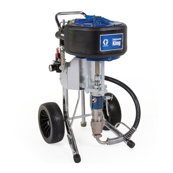
Contractor King
Packages and Pumps
High pressure spray packages for applying high performance coatings. For professional
use only.
Important Safety Instructions
Read all warnings and instructions in this
manual and related manuals before
using the equipment. Save these
instructions.
See page 3 for model information, including maximum
working pressure and approvals.
Related Manuals
Manual in
Description
English
311254
Silver Gun and Silver HP Gun
3A9122
Lower Manual (pump)
333507
Hopper Kit
3A9126
Zinc Circulation Kit
3A9127
Air Filter Lubrication, Air Regulation Kits
3A9129
Lift Ring Kit
3A9128
Paint Filter Kit
™
Spray
3A9121A
EN
Advertisement
Table of Contents
Troubleshooting

Subscribe to Our Youtube Channel
Related Manuals for Graco Contractor King 279005


Summary of Contents for Graco Contractor King 279005
- Page 1 Instructions ™ Contractor King Spray 3A9121A Packages and Pumps High pressure spray packages for applying high performance coatings. For professional use only. Important Safety Instructions Read all warnings and instructions in this manual and related manuals before using the equipment. Save these instructions.
-
Page 2: Table Of Contents
Run Motor Manually ......20 Graco Standard Warranty....45 Troubleshooting - General . -
Page 3: Models
Models Maximum Sprayer Hose Pressure Pump Working Fluid Model Description (Whip Hose) Ratio Size Pressure 279005 Bare 279006 Silver - 2 finger trigger 3/8 in. x 50 ft Complete (1/4 in. x 6 ft) 279026 Silver - 4 finger trigger 45:1 290 cc 4500 psi... -
Page 4: Warnings
Warnings Warnings The following warnings are for the setup, use, grounding, maintenance, and repair of this equipment. The exclamation point symbol alerts you to a general warning and the hazard symbols refer to procedure-specific risks. When these symbols appear in the body of this manual or on warning labels, refer back to these Warnings. Product-specific hazard symbols and warnings not covered in this section may appear throughout the body of this manual where applicable. - Page 5 Warnings WARNING MOVING PARTS HAZARD Moving parts can pinch, cut or amputate fingers and other body parts. • Keep clear of moving parts. • Do not operate equipment with protective guards or covers removed. • Equipment can start without warning. Before checking, moving, or servicing equipment, follow the Pressure Relief Procedure and disconnect all power sources.
-
Page 6: Component Identification
Component Identification Component Identification Suction Hose with Swivel and Tube Air Inlet, 1 in. npt(f) on claw fitting Pump Fluid Outlet Bleed Type Master Air Valve (required) PG Pump Guard Pilot Valve Manual Override Buttons Air Pressure Relief Valve Spray Gun Air Pressure Gauge De-Ice Control (bleed air) Packing Nut... -
Page 7: System Components
System Components System Components Air Regulator Adjustment (G) Adjusts air pressure to the motor and fluid outlet * Required system components. pressure of pump. Locate it close to the pump. Read air pressure on air pressure gauge (E). * Bleed Type Master Air Valve (B) * Fluid Drain/Purge Valve (J) Open valve to relieve pressure and when flushing or priming pump. -
Page 8: Grounding
Grounding Grounding Grounding Installation Tools Required: • Grounding wires and clamps for pails The equipment must be grounded to reduce the risk of static sparking. Static sparking can cause fumes • Two 5 gallon (19 liter) metal pails to ignite or explode. Grounding provides an escape wire for the electric current. -
Page 9: Setup
Setup Setup 4. Replace pump guard (PG). 5. Attach suction hose (N) and tighten. 6. Attach electrically conductive fluid hose (W) to To avoid tip over, ensure cart is on a flat and level pump outlet (P) and tighten. surface. Failure to do so could result in injury or damage to equipment. -
Page 10: Pressure Relief Procedure
Pressure Relief Procedure Pressure Relief Procedure 3. Disengage gun trigger lock. Follow the Pressure Relief Procedure whenever you see this symbol. This equipment stays pressurized until pressure is manually relieved. To help prevent serious injury from pressurized fluid, such as skin injection, splashing fluid and moving parts, follow the Pressure Relief Procedure when you stop spraying and before cleaning, checking, or servicing equipment. -
Page 11: Clearing A Clogged Tip
Clearing a Clogged Tip Clearing a Clogged Tip 6. Drain fluid. To drain fluid, slowly open all fluid drain valves, including fluid drain/purge valve (J), in system into a waste pail. If there is a return tube, open return line ball valve. Close valve after fluid is drained. -
Page 12: Flush
Flush Flush 6. Turn air regulator adjustment knob (G) counterclockwise until air pressure gauge (E) reads zero. To avoid fire and explosion, always ground equipment and waste container. To avoid static sparking and injury from splashing, always flush at lower possible pressure. Flush the Pump: •... - Page 13 Flush b. Trigger gun, slowly turn air regulator 9. If flushing through drain/purge valve: adjustment knob (G) clockwise until pump a. Place drain tube in a grounded waste pail. beings to cycle and a steady stream comes Open fluid drain/purge valve (J) slightly by from gun.
- Page 14 Flush e. When clean solvent flows from drain tube close fluid drain/purge valve (J) by rotating clockwise. Pump will stall. Stop the pump with the rod buried in the pump. g. Turn the air regulator adjustment knob (G) counterclockwise until air pressure gauge (E) reads zero.
-
Page 15: Prime
Prime Prime 5. Open bleed type master air valve (B). 1. Perform the Pressure Relief Procedure, page 10. 2. Engage the gun trigger lock. Remove tip and tip guard from gun. 3. Place suction tube in the material that will be sprayed. - Page 16 Prime b. Start the pump by rotating the air regulator b. Trigger gun, slowly open air regulator adjustment knob (G) clockwise until pump adjustment knob (G) until pump beings to cycle begins to move. and a steady stream comes from gun. Trigger gun for 10-15 seconds.
-
Page 17: Spray
Spray Spray 7. Disengage gun trigger lock. NOTICE Running the pump while dry will cause the pump to quickly accelerate to a high speed and cause dam- age. To avoid damage, do not allow pump to run dry. NOTE: When spraying in enclosed areas, such as storage tanks, locate the pump outside the area. -
Page 18: Maintenance
1. Perform the Flush procedure on page 12. 2. Perform the Prime procedure on page 15. Graco does not require lubrication beyond the grease installed at the factory or through regular maintenance. 3. Check packing nut (F). Adjust packings and replace With good quality compressed air and normal ambient TSL as necessary. - Page 19 Maintenance Add Lubrication Methods for adding lubrication are described below. Lubricate Air Valve Perform these steps annually, or more often depending on your duty cycle, air pressure, and air quality. Use a high quality lithium-based grease. • Remove and disassemble the air valve (see Remove Pump, page 23).
-
Page 20: Run Motor Manually
Maintenance Run Motor Manually 3. If a pilot valve is stuck in the open position or the pilot signal is leaking: a. Press the button on the opposite end from where the motor stopped and hold it in. This will cause the motor to stroke to the other end. b. -
Page 21: Troubleshooting - General
Troubleshooting - General Troubleshooting - General 1. Perform Pressure Relief Procedure, page 10. 2. Check all possible causes and problems before disassembling pump. * To determine if fluid hose or gun is obstructed, follow the Pressure Relief Procedure, page 10. Disconnect fluid hose and place a container at NOTE: To find parts lists for the parts identified in the pump fluid outlet to catch any fluid. -
Page 22: Repair
Repair Repair Remove Lower 5. Disconnect fluid hose (W). Hold pump outlet fitting (P) with a wrench to keep it from loosening while you disconnect fluid hose. Required Tools: NOTE: Note the relative position of pump fluid outlet (P) • Set of adjustable wrenches to inlet of motor for easier reassembly alignment. -
Page 23: Remove Pump
Repair Remove Pump 5. Loosen jam nut. 1. Follow Prepare to Service Lower, page 22. 2. Use a flathead screwdriver to remove the pump guard (PG). 3. Remove rod coupling. 6. Spin pump to remove. 4. If using a cart-mounted unit, tip the cart onto its back. -
Page 24: Install Pump
Repair Install Pump 3. Re-install rod coupling (CP) and pump guard (PG). 1. If using a cart-mounted unit, tip the cart onto its back. Threads even with top surface Jam nut tight to bottom surface 4. Tighten jam nut. 2. Install pump by threading it into place. Threads should be even with the top surface. -
Page 25: Troubleshooting - Air Motor
Troubleshooting - Air Motor Troubleshooting - Air Motor 2. Check all possible causes and problems before disassembling pump. * To determine if fluid hose or gun is obstructed, follow the Pressure Relief Procedure, page 10. Disconnect NOTE: To find parts lists for the parts identified in the fluid hose and place a container at pump fluid outlet to troubleshooting tables, see page numbers listed in the catch any fluid. - Page 26 Troubleshooting - Air Motor Problem Cause Solution Motor stalled at top of stroke with no Top pilot valve (D) is not exhausting. Disconnect pilot line for that pilot. If exhaust at top pilot. Usually ice in the pilot or pilot motor changes over, top pilot is exhaust port.
-
Page 27: Air Motor Repair
Air Motor Repair Air Motor Repair Ice in Air Motor Repair Air Valve When compressed air is exhausted, the sudden drop in pressure causes the air temperature to drop below the freezing point. This causes any water liquid or vapor to turn to ice. - Page 28 (301) and can be reused. Replace Seals or Rebuild Air Valve Reassemble the Air Valve Contact Graco to order kits for your pump. 1. The piston (304) and u-cup seals (306) come Disassemble the Air Valve pre-assembled. Lubricate the u-cup seals (306) on both ends of the piston (304) and install it in the 1.
-
Page 29: Replace Pilot Valve
Air Motor Repair Replace Pilot Valve Disassemble the Air Motor 1. Follow steps in Prepare to Service Lower, page 22. 2. Disconnect pilot valve air lines (37, 38) from the air 1. Stop the pump at the middle of its stroke. Relieve valve (30). -
Page 30: Reassemble The Air Motor
Air Motor Repair Reassemble the Air Motor NOTE: The piston and rod are epoxied together and only available as an assembly (10). Do not attempt to take apart the piston and rod assembly. NOTE: For additional parts information, see Parts, page 34. -
Page 31: Piston Seal Replacement
Air Motor Repair Piston Seal Replacement 6. Slide the piston assembly (10) down into the cylinder (14). Be sure the o-ring (13) stays in place. Work it carefully into the groove. Removal 7. Lubricate and install the o-ring (6) on the top cover Refer to the illustration on the following page for the (22). - Page 32 Air Motor Repair 6. Loosen two screws (27), remove top two (27) 7. Remove six bolts (31) on top of motor cover (22), screws, loosen lower two (27) screws to valve then remove cover. assembly (30) out of the way. Retain top gasket 8.
- Page 33 Air Motor Repair Replacement 5. Replace motor cover (22). NOTE: Use the image on the previous page for 6. Re-install top gasket (24) and screws (27) halfway reference when following these steps. onto manifold (25). 1. Use grease to lubricate piston seal (13). 7.
-
Page 34: Parts
Parts Parts Contractor King Parts Ref. Torque 50-60 ft-lb (68-81 N•m) 75-80 ft-lb (100-110 N•m) 17-23 ft-lb (23-31 N•m) 75-85 in-lb (9-10 N•m) 3A9121A... -
Page 35: Contractor King Parts List
Parts Contractor King Parts List Ref. Part Description Qty. Ref. Part Description Qty. LOWER, Contractor King 25U755 FRAME, Contractor King 19D951 180 cc 276974 CAP, leg 19D952 220 cc MOTOR, air, 6500, Contractor 19D954 290 cc 100133 WASHER, lock, 3/8 15M914 NUT, jam 100101 SCREW, cap, hex hd. -
Page 36: Xl6500 Air Motor Parts
Parts XL6500 Air Motor Parts Ref. Torque 33 +/- 3 ft-lb (45 +/- 4 N•m) 40 +/- 3 ft-lb (61 +/- 7 N•m) 80 +/- 5 in-lb (108 +/- 7 N•m) 12 +/- 3 in-lb (16 +/- 4 N•m) 80 +/- 5 in-lb (108 +/- 7 N•m) 3A9121A... -
Page 37: Xl6500 Air Motor Parts List
Parts XL6500 Air Motor Parts List Ref. Part Description Qty. Ref. Part Description Qty. 17S075 FOAM, temp barrier, poppet 17V316 COVER, bottom, motor, XL6500, 33★ 17M851 GASKET, poppet housing mach, includes 2, 3, 4, 5 17V571 KIT, poppet housing, includes 2★... -
Page 38: Air Valve Parts (17V344 - Standard Valve)
Parts Air Valve Parts (17V344 - Standard Valve) Apply high quality lithium grease. Blue thread sealant. ti37411a 3A9121A... -
Page 39: Air Valve Parts List
Parts Air Valve Parts List Ref. Part Description Qty. Ref. Part Description Qty. 316 17N617 CAP, valve, air, XL, machined HOUSING, air valve, XL, machined 317* 104010 PACKING, o-ring 302 115671 FITTING, connector, male 318* 154741 PACKING, o-ring 303 24Z604 VALVE, needle, assembly 319 17A511 PIN, reset, XL air valve PISTON, air valve, XL 320 557832 RING, retaining... -
Page 40: Performance Charts
Performance Charts Performance Charts Calculate Fluid Outlet Pressure Calculate Pump Air Flow/Consumption To calculate fluid outlet pressure (psi/MPa/bar) at a specific fluid flow (gpm/lpm) and operating air pressure To calculate pump air/consumption (scfm or m /min) at (psi/MPa/bar), use the following instructions and pump a specific fluid flow (gpm/lpm) and air pressure data charts. - Page 41 Performance Charts 60:1 Cycles Per Minute (cpm) 34-37 49-51 64-66 7000 (482) (8.5) 6000 (414) (7.1) 5000 (345) (5.6) 4000 (276) Fluid Pressure Air Flow (4.2) psi (bar) scfm (m /min) 3000 (207) (2.8) 2000 (138) 1000 (69) (1.4) Fluid Flow gpm (lpm) 70:1 Cycles Per Minute (cpm) 20-21...
-
Page 42: Technical Specifications
Technical Specifications Technical Specifications Contractor King Spray Packages Metric Maximum air inlet pressure to sprayer 150 psi 1 MPa, 10.3 bar Stroke length (nominal) 4.75 in. 12.0 cm Maximum pump speed (Do not exceed maximum recommended speed of 60 cycles per minute fluid pump, to prevent premature pump wear) Ambient Temperature 32 - 140 °F... -
Page 43: Additional Eac Requirements
Individual parts should be sorted by material and disposed of properly. Key construction materials can be found in the Materials of Construction Section. Series (4th Part Number Series Graco Date Month Year (2nd and 3rd character) (5th-10th) (11th-16th) -
Page 44: California Proposition 65
California Proposition 65 California Proposition 65 CALIFORNIA RESIDENTS WARNING: Cancer and reproductive harm – www.P65warnings.ca.gov. 3A9121A... -
Page 45: Graco Standard Warranty
With the exception of any special, extended, or limited warranty published by Graco, Graco will, for a period of twelve months from the date of sale, repair or replace any part of the equipment determined by Graco to be defective. - Page 46 Original instructions. This manual contains English. MM 3A9121 Graco Headquarters: Minneapolis International Offices: Belgium, China, Japan, Korea GRACO INC. AND SUBSIDIARIES • P.O. BOX 1441 • MINNEAPOLIS MN 55440-1441 • USA Copyright 2022, Graco Inc. All Graco manufacturing locations are registered to ISO 9001. www.graco.com...
Need help?
Do you have a question about the Contractor King 279005 and is the answer not in the manual?
Questions and answers