Graco PT2500 Instructions-Parts List Manual
Electric airless paint sprayer 1/4 gallon per minute, 120 vac, 60 hz, 3000 psi (21.0 mpa, 210 bar) maximum working pressure
Hide thumbs
Also See for PT2500:
- Instructions and parts list (24 pages) ,
- Instructions manual (24 pages) ,
- Instructions-parts list manual (24 pages)
Table of Contents
Advertisement
Quick Links
INSTRUCTIONS–PARTS LIST
This manual contains important
warnings and information.
READ AND RETAIN FOR REFERENCE
1/4 GALLON PER MINUTE, 120 VAC, 60 HZ
PT2500
Electric Airless Paint Sprayer
3000 psi (21.0 MPa, 210 bar) Maximum Working Pressure
Model 218–796, Series E
Basic Sprayer without hose or gun.
Model 218–501, Series C
Complete Sprayer with hose and gun.
U.S. Patent No. 4,616,982
U.K. Patent No. 2,165,591
Other Foreign Patents Pending
Always Professional Results
GRACO INC. P.O. BOX 1441 MINNEAPOLIS, MN 55440–1441
COPYRIGHT 1995, GRACO INC.
Graco Inc. is registered to I.S. EN ISO 9001
307–711
Rev. M
Supersedes L
and PCN M
Advertisement
Table of Contents

Subscribe to Our Youtube Channel
Related Manuals for Graco PT2500


Summary of Contents for Graco PT2500
- Page 1 Complete Sprayer with hose and gun. U.S. Patent No. 4,616,982 U.K. Patent No. 2,165,591 Other Foreign Patents Pending Always Professional Results GRACO INC. P.O. BOX 1441 MINNEAPOLIS, MN 55440–1441 COPYRIGHT 1995, GRACO INC. Graco Inc. is registered to I.S. EN ISO 9001...
-
Page 2: Manual Change Summary
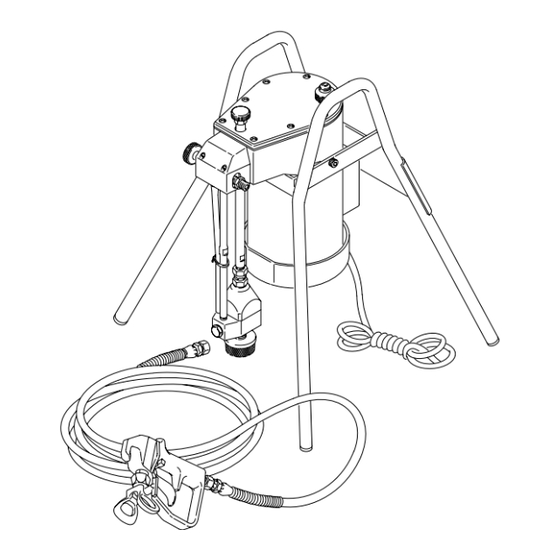
German 186–041 the following labels to apply to your sprayer. Apply the label at A Greek 186–045 for the best visibility. Order the labels directly from your Graco Korean 186–049 distributor without charge. English 185–953... - Page 3 Sprayer Description Decrease the pressure (counterclockwise). Increase the pressure (clockwise). Open the valve (counterclockwise). Close the valve (clockwise). Hydraulic pump Rac IV DripLess tip guard and spray tip Pressure control knob Hydraulic oil fill cap 11 ON/OFF switch 18 Motor 21 Diaphragm 22 Paint pump 27 Strainer...
-
Page 4: Warning Symbol
This equipment is for professional use only. Read all instruction manuals, tags, and labels before operating the equipment. Use the equipment only for its intended purpose. If you are not sure, call Graco Technical Assis- tance at 1–800–543–0339. Do not alter or modify this equipment. - Page 5 WARNING WARNING INJECTION HAZARD Spray from the gun, leaks or ruptured components can inject fluid into your body and cause ex- tremely serious injury, including the need for amputation. Fluid splashed in the eyes or on the skin can also cause serious injury. Fluid injected into the skin is a serious injury.
-
Page 6: Fire And Explosion Hazard
WARNING WARNING FIRE AND EXPLOSION HAZARD Improper grounding, poor ventilation, open flames or sparks can cause a hazardous condition and result in a fire or explosion and serious injury. If there is any static sparking or you feel an electric shock while using this equipment, stop spraying immediately. - Page 7 (5). The oil should be 25 mm from the top of the plate. Fig. 1 If the oil is low, fill as necessary with lightweight hy- draulic oil; use only Graco Hydraulic Oil, Part No. 218–797. Install the fill cap. See Fig. 1. Decrease pressure (counterclockwise).
-
Page 8: Pressure Relief Procedure
Startup If you suspect that the spray tip or hose is completely CAUTION clogged, or that pressure has not been fully relieved after following the steps above , VERY SLOWLY loos- The wallet sized warning card provided with the gun en the tip guard retaining nut or hose end coupling to should be kept with the operator at all times. - Page 9 Startup 6. Turn the bypass valve (66) clockwise (finger tight) 8. Whenever you stop spraying, even for a moment, al- to close it; this allows the pump to build up pressure. ways set the trigger safety lever to prevent acciden- tally trigger the gun.
- Page 10 Startup 16. If the tip is still clogged , lock the trigger safety lever, CAUTION shut off and unplug the sprayer, and open the bypass valve one turn counterclockwise. Disassemble the Never start the electric motor with the inlet valve tip in the reverse order of assembly (see manual removed to avoid damaging the diaphragm.
- Page 11 Notes...
-
Page 12: Maintenance Intervals
Maintenance 3. Check to be sure the trigger safety lever is locked. CAUTION Remove the spray tip from the gun. Unlock the safety lever. Hold a metal part of the gun firmly to the side Thorough flushing and proper maintenance are of a grounded metal pail. - Page 13 Maintenance 5. Open the bypass valve (66) ONE turn counter- 3. Set the sprayer upright. Increase the pressure con- clockwise. trol setting half way. Turn on the sprayer for a few se- conds, then turn it OFF. 6. Raise the paint pump above the solvent, turn on the 4.
- Page 14 Contaminants can cause damage to the hydraulic system. 4. Fill the hydraulic pump housing with 16.5 ounces (55 ml) of Graco lightweight hydraulic oil. Reinstall the fill cap. 5. Plug in the sprayer. Turn the pressure control (4) fully counterclockwise (no pressure).
- Page 15 Notes...
-
Page 16: Application Methods
Application Methods Always hold the gun perpendicular to the surface and The best way to control the rate of coverage is with the gun tip size. A small tip orifice applies less paint. A larger keep the gun at an even 12 to 14 inches (300 to 356 mm) from the surface you are spraying. -
Page 17: Troubleshooting
Troubleshooting NOTE: If your sprayer is not operating well, or will not op- WARNING erate at all, check for obvious problems first. Follow the Startup procedure exactly (see page 8). Then if the INJECTION HAZARD sprayer won’t start, use the Troubleshooting Chart for To reduce the risk of serious injury, help in identifying the possible cause. - Page 18 See page 19, Diaphragm, step 9 Hydraulic oil level low or empty See page 14. Wrong grade of hydraulic oil or Use only Graco approved hydraulic wrong fluid in hydraulic system oil, part no. 218–797 Inlet valve not tight Tighten; see page 14.
- Page 19 Service Repairs, other than those for which instructions are given 7. The last coil on one end of the spring is turned in. below, should be performed by a trained and qualified re- Place this end over the stud in the plug (28d). Install pair agency.
- Page 20 Service 14. Lubricate the screws (25) and then install and torque 15. Check the hydraulic oil level and add Graco-ap- them to 170–200 in-lb (19–23 N.m ). proved oil as necessary until the level is 1 inch (25 mm) from the top of the plate. See Fig. 11.
- Page 21 Parts Model 223–635, Series C, with a hose and a gun. Lubricate the threads. Torque to 40–45 in–lb (54–60 N.m). Torque to 130–140 in–lb (15–16 N.m). Apply PTFE tape to the top and bottom threads. See Detail A, page 23. Torque to 70–90 in–lb (8–10 N.m).
-
Page 22: Starter Switch
Parts Model 218–796, Series E Ref. Includes items 1 to 99 Part No. Description Qty. 107–519 SEAL, shaft Model 218–501, Series C 108–288 CAPSCREW, sch, M6 x 16 Includes items 1 to 102 108–165 PACKING, o–ring, Buna–N 181–032 SEAL, tube NOTE: Part numbers and drawings for items 10–12, 180–466 ROD, displacement, 5 gallon... - Page 23 Parts Ref. Part No. Description Qty. DETAIL B 105–659 TOGGLE BOOT The starter 105–679 SWITCH, toggle switch 105–774 PLATE, switch, ON/OFF is located in this 106–013 STRAIN RELIEF BUSHING box. 110–900 .STARTER SWITCH 180–406 HOUSING, diaphragm 218–727 DIAPHRAGM ASSEMBLY 224–624 PUMP HOUSING KIT Includes 22a, 22b BLACK...
-
Page 24: Technical Data
Graco distributor to the original purchaser for use. With the exception of any special extended or limited warranty published by Graco, Graco will, for a period of twelve months from the date of sale, repair or replace any part of the equipment determined by Graco to be defective.
Need help?
Do you have a question about the PT2500 and is the answer not in the manual?
Questions and answers