Table of Contents
Advertisement
Quick Links
Description and operating instructions
i Rail Switch Family
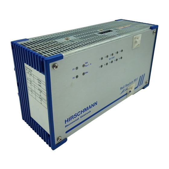
FDX
P1
1
3
5
7
9
Port 1 - 4
DA / STAT
P2
Stby
2
4
6
8
10
Rail Switch RS1-FX/FX
i
9
1
10
039587001010998000
Printed in Germany
2
3
4
5
6
7
8
Redundancy Manager
RM1
Fault
DA/STAT
Port
+24 V
+24 V*
P1
1
3
5
7
9
P2
2
4
8
10
6
CPU
RESET
V24
RS1-...
Order no.
943 606-0...
RM1
Order no.
943 632-001
The i Rail Switch modules allow
switched Ethernet networks in accordance
with IEEE standard 802.3 using copper tech-
nology and backbones in accordance with
IEEE standard 802.3u using copper techno-
logy or optical waveguide (F/O) in line and
ring structure to be constructed. The switch
modules are plugged onto the standard bar.
The RS1s (Rail Switch) have eight 10 Mbit/s
twisted pair (TP) ports and two 100 Mbit/s
ports. Depending on the type of RS1 the
100 Mbit/s ports to attach further more RS1
are supplied with FX, TX interfaces or both.
It is possible to connect up to eight pieces
of terminal equipment or other TP seg-
ments to the 10 Mbit/s ports using TPs.
The built-in control intelligence allows the
redundant coupling of several network seg-
ments to a higher network segment.
An RM1 (Redundancy Manager) has eight
10 Mbit/s TP ports and two free slots for
100 Mbit/s modules. The 100 Mbit/s ports
allow to close a line-structured backbone to
a ring with redundancy function.
The 100 Mbit/s module ETSXM-01TP(FE)
has one TX port.
The 100 Mbit/s module ETSXM-01MM(FE)
has one FX port.
1
Advertisement
Table of Contents

Related Manuals for Hirschmann RS1 Series


Summary of Contents for Hirschmann RS1 Series
- Page 1 RS1-… Order no. Description and operating instructions 943 606-0… i Rail Switch Family Order no. 943 632-001 The i Rail Switch modules allow switched Ethernet networks in accordance with IEEE standard 802.3 using copper tech- nology and backbones in accordance with Port 1 - 4 DA / STAT Stby...
- Page 2 This packing can be reused. Copyright © Be sure to observe the following precauti- © Richard Hirschmann GmbH & Co. 1998 ons for electrostatic sensitive devices when All Rights Reserved handling the components: Establish electrical potential equality bet- ween yourself and your surroundings, e.g.
- Page 3 1. Functional description 1.4 REDUNDANCY FUNCTIONS 1.6 CONTROLS Backbone as a ring 12-pin DIP switch (RS1) With an RM1 you can close a line structured 10-pin DIP switch (RM1) The ports of an RS1/RM1 represent a termi- RS1 backbone to a redundant ring. Using the 12-pin DIP switch on the top of nal connection for the connected LAN seg- If one section fails the ring structure chan-...
- Page 4 100 Mbit/s connection supply voltage is electrically isolated from 2. Configuration Two ports allow a 100 Mbit/s backbone to the housing. be constructed. 2.1 LINE STRUCTURE – Indicator contact: Contract interrupt The RS1s enable backbones in line structu- – RS1-FX/FX: two ports in accordance with indicates the following by means of a 100BASE-FX (SC sockets, multimode) res to be built up.
- Page 5 Fig. 7: Redundant ring structure Ring 1 redundante redundante coupling coupling control line control line Ring 1 <–> Ring 2 Ring 1 <–> Ring 3 Ring 3 Ring 2 For coupling network segments the ports 1 and 2 For coupling network segments the ports 1 or 2 are to use on these RS1.
- Page 6 Check whether the package was deliver- Attach the first mounting bracket with Hirschmann office. You can find the addres- ed complete (see scope of delivery). the 4 screws. ses of our contract partners Check the individual parts for transport Repeat on the other side.
- Page 7 5. Technical data General data Operating voltage DC 18 to 32 V safety extra-low voltage (SELV) (redundant inputs decoupled) Current consumption 500 mA (RS1) and 1.2A (RM1) respectively maximum, at 24 VDC Overload current protection at input non-changeable thermal fuse Dimensions W x H x D 210 mm x 125 mm x 85 mm (RS1) and 434 mm x 44 mm x 279 mm (RM1) respectively 8,3 in x 4,9 in x 3,3 in (RS1) and 17,1 in x 1,7 in x 11 in (RM1) respectively...
- Page 8 (amended by Direc- Richard Hirschmann GmbH & Co. tives 91/263/EEC, 92/31/EEC and The precondition for compliance with EMC Network Systems Division 93/68/EEC). limit values is strict adherence to the con- Stuttgarter Straße 45-51...
Need help?
Do you have a question about the RS1 Series and is the answer not in the manual?
Questions and answers