
Related Manuals for Hirschmann Octopus II


Summary of Contents for Hirschmann Octopus II
- Page 1 User Manual Installation Managed IP65/67 Switch Octopus II Installation Octopus II Technical support Release 06 10/2018 https://hirschmann-support.belden.com...
- Page 2 In addition, we refer to the conditions of use specified in the license contract. You can get the latest version of this manual on the Internet at the Hirschmann product site (www.hirschmann.com). Hirschmann Automation and Control GmbH Stuttgarter Str.
-
Page 3: Table Of Contents
Checking the package contents Installing and grounding the device 2.2.1 Installing the device 2.2.2 Grounding the device Connecting the ferrite Connecting the power supply and the signal contact lines 2.4.1 Supply voltage with the characteristic value BB Installation Octopus II Release 06 10/2018... - Page 4 2.4.7 Supply voltage with the characteristic value PP 2.4.8 Signal contact Operating the device Connecting data cables Filling out the inscription label Making basic settings Monitoring the ambient air temperature Maintenance and service Disassembly Technical data Further support Installation Octopus II Release 06 10/2018...
-
Page 5: Safety Instructions
Operate the device with undamaged components exclusively. The device is free of any service components. In case of a damaged or malfunctioning device, turn off the supply voltage and return the device to Hirschmann for inspection. Qualification requirements for personnel ... - Page 6 Certified usage Use the product only for the application cases described in the Hirschmann product information, including this manual. Operate the product only according to the technical specifications. See “Technical data” on page 49. Connect to the product only components suitable for the requirements of the specific application case.
- Page 7 Exclusively for The power supply cable is suitable for the voltage, the current and the device variants physical load. Hirschmann recommends a wire diameter of 0.5 mm² to featuring supply 0.75 mm² (AWG20 up to AWG18). voltage with The following requirements are alternatively complied with:...
- Page 8 The power supply cable is suitable for the voltage, the current and the featuring supply physical load. The wire diameter is at least AWG18 (0.75 mm²). voltage with The power supply inputs of the Octopus II device must not be grounded. characteristic value PP: The following requirements are alternatively complied with: Alternative 1 ...
- Page 9 National and international safety regulations Verify that the electrical installation meets local or nationally applicable safety regulations. E marking The labeled devices comply with the regulations contained in the following European directive(s): Installation Octopus II Release 06 10/2018...
- Page 10 In accordance with the above-named EU directive(s), the EU conformity declaration will be at the disposal of the relevant authorities at the following address: Hirschmann Automation and Control GmbH Stuttgarter Str. 45-51 72654 Neckartenzlingen Germany www.hirschmann.com...
- Page 11 Recycling note After usage, this device must be disposed of properly as electronic waste, in accordance with the current disposal regulations of your county, state, and country. Installation Octopus II Release 06 10/2018...
-
Page 12: About This Manual
Documentation mentioned in the "Installation" user manual that is not supplied with your device in print can be found as PDF download on the Internet at the Hirschmann product pages (www.hirschmann.com). Installation Octopus II Release 06 10/2018... -
Page 13: Key
The symbols used in this manual have the following meanings: Listing Work step Subheading Installation Octopus II Release 06 10/2018... -
Page 14: Description
Description General description The Octopus II devices are designed for the special requirements of industrial automation. They meet the relevant industry standards, provide very high operational reliability, even under extreme conditions, and also long-term reliability and flexibility. You have numerous options of combining the device characteristics. You can... - Page 15 Item Characteristic Characteri Description stic value 1 ... 2 Product Octopus II device Data rate Fast Ethernet ports Fast Ethernet ports and Gigabit Ethernet ports Hardware type Standard Standard with PoE(+) (hyphen) – 6 ... 7 Number 0 × PoE(+) ports PoE(+) ports 8 ×...
- Page 16 See table 7 on page 18. 24 ... 25 Software packages Reserved 26 ... 27 Customer-specific Hirschmann standard version Hirschmann Angled Hirschmann Power Supply Side Table 6: Device name and product code Installation Octopus II Release 06 10/2018...
- Page 17 HiOS Layer 2 Advanced HiOS Layer 3 Standard 32 ... 36 Software version 04.1. Software-Version 04.1 XX.X. Current software version 37 ... 38 Maintenance Bugfix version 00 Current bugfix version Table 6: Device name and product code Installation Octopus II Release 06 10/2018...
- Page 18 Application case Certificates and declarations Characteristic value Standard applications EN 60950-1 EN 61131-2 cUL 60950-1 Navy applications DNV GL Railway applications EN 50121-4 (trackside) Railway applications (in EN 50155 vehicles) Motor vehicle applications E1 Table 7: Assignment: application cases, certificates and declarations, characteristic values...
- Page 19 Port type Built-in transceivers Version Characteristic value 1M 1S 1P 1L 1A 1B 1C 1D 4M 4S 4P 4L 4A 4B 4C 4D 5M 5S 5P 5L 5A 5B 5C 5D 1000 Mbit/s M-SFP-SX/LC-EEC F/O port QODC M-SFP-LX/LC-EEC QODC M-SFP-LH/LC-EEC QODC M-SFP-LH+/LC EEC QODC...
- Page 20 Port type Built-in transceivers Version Characteristic value 1M 1S 1P 1L 1A 1B 1C 1D 4M 4S 4P 4L 4A 4B 4C 4D 5M 5S 5P 5L 5A 5B 5C 5D 100 Mbit/s F/ M-FAST SFP-MM/LC EEC V1 O port QODC M-FAST SFP-SM/LC EEC QODC...
-
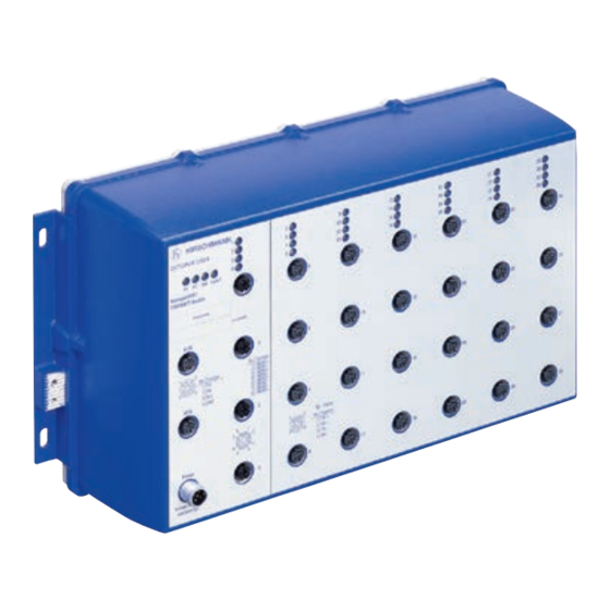
Page 21: Device View
Above: front of device Below: bottom of device 3a 3b Power RM Status Produktcode IP-ADDRESS V.24 Table 9: Device view Hole for mounting LED display elements for device status Table 10: Description of the device view Installation Octopus II Release 06 10/2018... - Page 22 Version: See table 8 on page 19. Alternatively: Data rate characteristic value 3 1000 Mbit/s F/O port Version: See table 8 on page 19. Table 10: Description of the device view Installation Octopus II Release 06 10/2018...
- Page 23 Note: The supply voltage connection is on the bottom of the device. Ground connection 5-pin, “A”-coded M12 socket for USB interface 4-pin, “A”-coded M12 socket for V.24 interface Label area for IP address of device Product code Table 10: Description of the device view Installation Octopus II Release 06 10/2018...
-
Page 24: Power Supply
These device variants optionally support PoE(+). Further information: “Support of PoE(+)” on page 26 1.4.6 Supply voltage with the characteristic value QQ A 4-pin, “T”-coded M12 power plug is available for the redundant supply of the device. Further information: Installation Octopus II Release 06 10/2018... -
Page 25: Supply Voltage With The Characteristic Value Pp
100 Mbit/s half-duplex mode, 100 Mbit/s full duplex mode 10 Mbit/s half-duplex mode, 10 Mbit/s full duplex mode Delivery state: Autonegotiation activated The socket housing is electrically connected with the device housing. Installation Octopus II Release 06 10/2018... -
Page 26: Support Of Poe(+)
PoE power supply unit with 150 W. This means that the maximum output available to all PoE end devices is in total 120 W. Connect only PoE-supplier devices whose data connections are located in the interior of the building and are specified as SELV circuits. Installation Octopus II Release 06 10/2018... - Page 27 IEEE 802.3 10BASE-T/100BASE-TX and IEEE 802.3af/at. 10/100/1000 Mbit/s PoE(+) port The 10/100/1000 Mbit/s PoE(+) port allows you to connect network components as a powered device (PD) according to standards IEEE 802.3 10BASE-T/100BASE-TX/1000BASE-T and IEEE 802.3af/at. Installation Octopus II Release 06 10/2018...
-
Page 28: Optical Fiber
V4: IP67 connector as per IEC 61076-3-106, variant 4 Q-ODC®: HUBER + SUHNER Table 12: Versions of F/O ports in the Octopus II devices The product code tells you which properties your device has. See “Device name and product code” on page 14. -
Page 29: Pin Assignments
Negative V M12 8-pin (“X”-coded) 10/100 Mbit/s 1000 Mbit/s BI_DB+ Negative V RX− BI_DB− Negative V BI_DA+ Positive V TX− BI_DA− Positive V — BI_DC+ — — BI_DC− — — BI_DD− — — BI_DD+ — Installation Octopus II Release 06 10/2018... -
Page 30: Display Elements
The boot parameters used when the a period device has been started differ from the boot parameters saved. Start the device again. flashes 4 times Device has detected a multiple IP address a period Installation Octopus II Release 06 10/2018... -
Page 31: Port Status
This interface is a 5-pin, “A”-coded M12 socket with shielding. Only connect the ACA21-M12/ACA22-M12 storage medium. You can obtain this as accessory: See “Accessories” on page 62. Installation Octopus II Release 06 10/2018... -
Page 32: Interface (External Management)
The socket housing is electrically connected to the housing of the device. Figure Function Transmit Data Receive Data N.C. Not used Ground Table 14: Pin assignment of the V.24 interface (M12 socket) Figure 1: Terminal cable for connecting an external Management Station Installation Octopus II Release 06 10/2018... -
Page 33: Signal Contact
The Terminal cable is available as an accessory. You will find a description of the V.24 interface in the “User Manual Basic Configuration” document. You can find further information on the Internet on the Hirschmann product pages under www.hirschmann.com Signal contact The signal contact is a potential-free relay contact. -
Page 34: Installation
Install this device solely in a switch cabinet or in an operating site with restricted access, to which maintenance staff have exclusive access. Failure to follow this instruction can result in death, serious injury, or equipment damage. Installation Octopus II Release 06 10/2018... -
Page 35: Grounding The Device
The device variants have a connection for protective grounding. Note: Use toothed washers to ensure good electrical conductivity at the connection. Ground the device via the provided M4 screw. M4x8 Installation Octopus II Release 06 10/2018... -
Page 36: Connecting The Ferrite
You find the prescribed tightening torque in chapter: See “Technical data” on page 49. The supply voltage is connected to the device casing through protective elements exclusively. You have the option of supplying the supply voltage redundantly, without load distribution. Installation Octopus II Release 06 10/2018... - Page 37 16.8 V DC ... 32 V DC voltages 1 and 2 4 Plus terminal of supply voltage 2 5 Signal contact Connect the electrical wires to the socket according to the pin assignment. Installation Octopus II Release 06 10/2018...
-
Page 38: Supply Voltage With The Characteristic Value Ff
You have the option of supplying the supply voltage redundantly, without load distribution. With a non-redundant supply of the supply voltage, the device reports the loss of a supply voltage. You can prevent this message by changing the configuration in the Management. Installation Octopus II Release 06 10/2018... -
Page 39: Supply Voltage With The Characteristic Value M9
A 4-pin 7/8" plug is available for the power supply to the device. You find the prescribed tightening torque in chapter: See “Technical data” on page 49. The supply voltage is connected to the device casing through protective elements exclusively. Installation Octopus II Release 06 10/2018... - Page 40 Plus terminal of the supply tolerances voltage 50.4 V DC ... 138 V DC P− Minus terminal of the supply P− voltage Connect the electrical wires to the socket according to the pin assignment. Installation Octopus II Release 06 10/2018...
-
Page 41: Supply Voltage With The Characteristic Value Qq
Supply voltage with the characteristic value PP Note: Exclusively use a PoE power supply unit with galvanic isolation. Hirschmann has tested the power supply unit PC150/110V/54V and recommends its use. You find the order number for the power supply unit, which is available as accessory, under: “Accessories”... - Page 42 Rated voltage range 24 V DC ... 48 V DC Voltage range incl. maximum tolerances 19 V DC ... 60 V DC Connect the electrical wires to the socket according to the pin assignment. Installation Octopus II Release 06 10/2018...
-
Page 43: Signal Contact
See “Requirements for connecting electrical wires” on page 6. Failure to follow this instruction can result in death, serious injury, or equipment damage. By connecting the supply voltage via a connector, you start the operation of the device. Installation Octopus II Release 06 10/2018... -
Page 44: Connecting Data Cables
Use SF/UTP cables as per ISO/IEC 11801:2002. Connect the data cables according to your requirements. Further information: “Ethernet ports” on page 25 Filling out the inscription label The information field for the IP address helps you identify your device. Installation Octopus II Release 06 10/2018... -
Page 45: Making Basic Settings
(read/write) V.24 data rate: 9600 Baud Ethernet ports: link status is not evaluated (signal contact) Optical ports: Full duplex TP ports: Autonegotiation RSTP (Rapid Spanning Tree) activated Installation Octopus II Release 06 10/2018... -
Page 46: Monitoring The Ambient Air Temperature
It is higher than the ambient air temperature. The maximum internal temperature of the device named in the technical data is a guideline that indicates to you that the maximum ambient air temperature has possibly been exceeded. Installation Octopus II Release 06 10/2018... -
Page 47: Maintenance And Service
Check regularly whether there is an updated version of the software that provides you with additional benefits. You find information and software downloads on the Hirschmann product pages on the Internet (http://www.hirschmann.com). Note: You find information on settling complaints on the Internet at http:// www.beldensolutions.com/en/Service/Repairs/index.phtml. -
Page 48: Disassembly
Failure to follow this instruction can result in death, serious injury, or equipment damage. Disable the supply voltage. Disconnect the data cables. Disconnect the power supply cables and signal lines. Disconnect the grounding. Installation Octopus II Release 06 10/2018... -
Page 49: Technical Data
5.3 lb-in (0.6 Nm) Power loss buffer >10 ms at 20.4 V DC Overload current Non-replaceable fuse protection at input Back-up fuse Nominal rating: 10 A ... 20 A Characteristic: slow blow Peak inrush current <7 A Installation Octopus II Release 06 10/2018... - Page 50 1 A ... 20 A OS20/OS30 Characteristic: slow blow Back-up fuse Nominal rating: 4 A ... 20 A OS24/OS34 Characteristic: slow blow Peak inrush current <3.5 A OS20/OS30 Peak inrush current <7 A OS24/OS34 Installation Octopus II Release 06 10/2018...
- Page 51 Devices with operating temperature characteristic value T (extended): 95 °C Humidity 5 % ... 100 % (also in condensing atmospheres) Air pressure min. 700 hPa (+9842 ft; +3000 m) max. 1060 hPa (−1312 ft; −400 m) Installation Octopus II Release 06 10/2018...
- Page 52 To preserve the suitability of your device for IP65/67, proceed as follows: Remove all provided transport protection caps and transport protection screws. Seal unused sockets and plugs with your desired type of protection screws which you can order separately. Installation Octopus II Release 06 10/2018...
- Page 53 Dimension drawings inch 338,2 13.31 326,2 12.84 308,8 12.16 39,3 39,4 39,3 0.15 0.16 0.15 1.85 94,8 10.28 3.73 92,7 3.65 10,9 0.43 Installation Octopus II Release 06 10/2018...
- Page 54 EMC and immunity Note: You will find detailed information on the certificates and declarations applying to your device in a separate overview. See table 7 on page 18. Installation Octopus II Release 06 10/2018...
- Page 55 EMC interference Standard Navy Railway Railway Motor vehicle emission applications applications applications applications (in applications (trackside) vehicles) Radiated emission EN 55032 Class A Class A Class A Class A Class A DNV GL Guidelines — EMC 1 — — — FCC 47 CFR Part 15 Class A Class A...
- Page 56 EMC interference Standard Navy Railway Railway Motor vehicle immunity applications applications applications applications (in applications (trackside) vehicles) Electrostatic discharge EN 61000-4-2 Contact discharge ±4 kV ±6 kV ±6 kV ±6 kV ±4 kV IEEE C37.90.3 EN 61000-4-2 Air discharge ±8 kV ±8 kV ±8 kV ±8 kV...
- Page 57 Stability Standard Navy Railway Railway applications (in Motor vehicle applications applications applications vehicles) applications (trackside) IEC 60068-2-6, test Fc Vibration 5 Hz ... 8.4 Hz with 2 Hz ... 13.2 Hz — Operating — 0.14 in (3.5 mm) with 0.04 in 5 Hz ...
- Page 58 Network range Note: The line lengths specified for the transceivers apply for the respective fiber data (fiber attenuation and BLP/ dispersion). Product code Mode Wave length Fiber System Example for F/O Fiber attenuation BLP/Dispersion M-FAST-SFP-... attenuation cable length -MM/LC... 1310 nm 50/125 µm 0 dB ...
- Page 59 Product code Mode Wave length Fiber System Example for F/O Fiber attenuation BLP /Dispersion M-SFP-... attenuation cable length -LX/LC... 1310 nm 9/125 µm 0 dB ... 9.5 dB 0 mi ... 10.87 mi 0.4 dB/km 3.5 ps/(nm×km) (0 km ... 17.5 km) -LH/LC...
- Page 60 Power consumption/power output, order numbers The order numbers correspond to the product codes of the devices. See “Device name and product code” on page 14. Device name Maximum Power output power consumption OS20-000800... 22 W 75 Btu (IT)/h OS20-001200... 26 W 87 Btu (IT)/h OS20-002000...
- Page 61 Only for device variants featuring supply voltage with characteristic value FF: 7/8" connectors, 5-pin Design: HH - Hirschmann Standard HA - Hirschmann with angled connector 1 × Only for device variants featuring supply voltage with characteristic value N9: 7/8" connectors, 4-pin Design: ...
- Page 62 Protection screw for M12 plug, metal, IP65/67 (10 pieces) 942 115-001 Connection cable with M12 connector, “D”-coded 934 497-00x Transition M12 “D”-coded to RJ45 934 498-001 Network management software Industrial HiVision 943 156-xxx PoE power supply unit (PC150/110V/54V) 942 242-001 Installation Octopus II Release 06 10/2018...
- Page 63 If your device has a shipping approval according to DNV GL, you find the approval mark printed on the device label. You will find out whether your device has other shipping approvals on the Hirschmann website at www.hirschmann.com in the product information.
-
Page 64: A Further Support
Further support Technical questions For technical questions, please contact any Hirschmann dealer in your area or Hirschmann directly. You find the addresses of our partners on the Internet at http:// www.hirschmann.com. A list of local telephone numbers and email addresses for technical support... - Page 65 Installation Octopus II Release 06 10/2018...
Need help?
Do you have a question about the Octopus II and is the answer not in the manual?
Questions and answers