Table of Contents
Advertisement
Quick Links
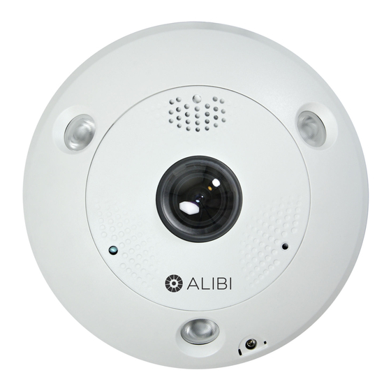
ALI-NS1012VRP Panoramic 12 MP IP Camera
Quick Installation Guide
This document guides you through the basic steps to install and configure the ALI-NS1012VRP camera. This
camera features:
1/1.7" progressive scan CMOS with 4000 × 3000 pixel resolution @ 30 fps
•
360° fisheye panoramic view
•
Multiple viewing modes
•
Internal microSD / SDHC / SDXC card slot for storage up to 256 GB (card not provided)
•
1
alarm IN and OUT
•
X
Built-in microphone and speaker, supports external microphone and speaker
•
50 ft IR range
•
Compatible with these accessories: ALI-AF8 flange adapter, ALI-AJ3 angled surface mount junction
•
box, ALI-AJ12 Pro VF turret flange.
For more information about the software features of this camera, please refer to the ALI-IP Camera
Firmware User Manual.
Speaker and microphone
Fisheye Lens
ALI-NS1012VRP camera
RJ-45 LAN
connector
Underside of camera with drop cables
www.observint.com
1
Bezel
IR LEDs (3)
Bezel lock screw
under cover.
Product
label
12 Vdc
Power
Audio
LINE IN
RS-485
Alarm
D+, D-
Audio
IN/OUT
LINE OUT
What's in the box
Your camera includes:
Camera assembly
•
Drill template
•
Waterproof Ethernet Fitting
•
Security L-wrench
•
Mounting screws and wall inserts
•
Installation guide (this document)
•
Alibi IP Camera Network Setup Guide
•
Security L-wrench and mounting hardware
Step 1.
Before installing the camera ...
The ALI-NS1012VRP camera can be installed on a ceiling, wall or table, or installed with any of the optional
accessories listed above.
1.
Check the package contents and make sure that the device in the package is in good condition and
all the assembly parts are included. NOTE: Do not remove the protective film on the lens until the
camera is mounted and you are ready to power it on.
2.
Make sure the mounting surface and fasteners are strong enough to withstand at least three times
the weight of the camera assembly and the mounting bracket (if used). For concrete or cement
block walls, use an expansion screw to secure the camera or mounting bracket.
3.
Make sure all the equipment that will be attached to the camera is power-off during the installation,
if possible.
4.
Check the specification of the products for the installation environment.
5.
Make sure the power supply is matched with the camera voltage and wattage specification to avoid
damage.
6.
Make sure that there are no reflective surface too close to the camera lens. The IR light from the
camera may reflect back into the lens causing reflection.
7.
Do not remove the dome cover film until the installation is finished. Dust or grease on the dome
cover will cause IR reflection. If there is dust or grease on the dome cover, clean the dome cover with
clean soft cloth and isopropyl alcohol.
Step 2.
Prepare the camera for installation
Remove the Bezel
1.
Remove the camera assembly from the packaging. Do not remove the plastic film from that covers
the lens at this time.
2.
Lay the camera on a clean, flat surface with the lens side up.
3.
Open the Bezel Lock Screw cover.
4.
Use the security L-wrench to fully unscrew the bezel lock screw. NOTE: The bezel lock screw is a
captive screw.
5.
Unsnap the cover from the camera assembly.
6.
Unsnap the bezel from the camera assembly. If the bezel cannot be separated from the camera
assembly, turn the camera base side up and push a small blade screwdriver into the slots shown in
the photo below to free the three bezel retention tabs from catches on the camera assembly.
Bezel
Bezel Lock Screw
Shown with cover removed
ALI-NS1012VRP_CQ
190924
Advertisement
Table of Contents

Related Manuals for ALIBI ALI-NS1012VRP


Summary of Contents for ALIBI ALI-NS1012VRP
- Page 1 Step 1. Before installing the camera ... Bezel Speaker and microphone The ALI-NS1012VRP camera can be installed on a ceiling, wall or table, or installed with any of the optional accessories listed above. IR LEDs (3) Fisheye Lens Check the package contents and make sure that the device in the package is in good condition and all the assembly parts are included.
- Page 2 Use the Drill Template provided to mark and drill the holes in the ceiling for the fasteners (mounting screws). Also drill a hole for the drop cables. For wall mount installation, orient the template so that the arrow points up (perpendicular to the plane of your surveillance target). For wall mount installation, the camera must be oriented so the “UP”...
- Page 3 Audio OUT drop cable. Alarm IN leads connect to the IN1 and G terminals, Alarm OUT leads connect Note: In the screen above, the tool can discover devices on other subnets. It will also list other Alibi to the 1A and 1B terminals.
- Page 4 1.1 Modify Network Parameters Run as administrator NOTE: If the camera LAN extension cable is attached to a Network Video Recorder (NVR), skip this step. The camera will receive network configuration settings from the NVR. Refer to the documentation available for your NVR firmware for more information.
- Page 5 In the Live View screen, click the Mounting Type icon representing how the camera is mounted (ceiling, wall or table). The icon selected will be orange, and a Save Succeeded message will appear in the lower right corner of the screen. You can hover the mouse cursor over a Display Mode icon to show its definition.
- Page 6 Wait for the format operation to complete before continuing. The card status should then be Behavior analysis: Line crossing detection, intrusion detection, region entrance detection, region exiting Normal, and the Free space should me nearly the Capacity of the card. detection, unattended baggage detection, object removal detection Interface Edit the percentages of the HDD allocated for Picture and Record data as needed.
Need help?
Do you have a question about the ALI-NS1012VRP and is the answer not in the manual?
Questions and answers