Advertisement
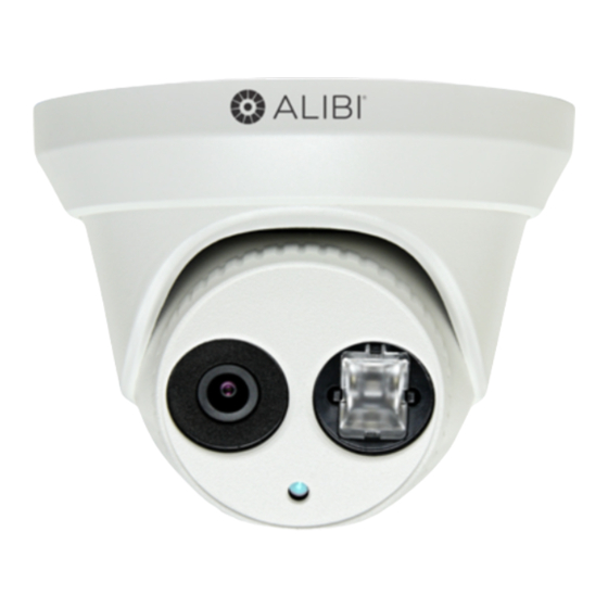
ALI-NS1034R 4 Megapixel IP
Turret Camera Quick Installation
Guide
This document guides you through the basic steps to install and configure the ALI-NS1034R camera. This
camera features:
4 Megapixel 1/2.8 in. CMOS progressive scan sensor
•
High definition (up to 2688 x 1520) video streaming and dual-stream video support
•
Video stream compression: H.264 standard and MJPEG
•
3D-DNR noise reduction and Digital Wide Dynamic Range (WDR)
•
Backlight compensation
•
Smart IR Array, 850 nm, 100 ft IR range
•
Dual power capable - Power over Ethernet (PoE) or 12 Vdc
•
Weatherproof - IP66 rated
•
For more information about the features of these cameras, please refer to the ALIBI™ IP Camera Software V2
User Manual.
Enclosure
Dome
What's in the box
Box contains this document with the items shown below.
Drill Template
Step 1.
Install the camera
1.
Determine the best fasteners for securing the camera to mounting surface. The mounting hardware
provided is suitable for most surfaces.
www.observint.com
1
Ethernet
connector
Power
Connector
Trim ring
IR LED
Lens
Documentation and
Installation Tools CD
Mounting
screws and
wall inserts
Weatherproof fitting
for Ethernet cable
2.
Remove the Trim Ring from the camera by
turning it clockwise about 15˚, and then
lifting it off the assembly.
3.
Determine how the drop cable will be
routed. It can be routed either through the
mounting surface or through the trim ring. If
routing it through the trim ring, remove one
of the side outlet plugs in the ring.
4.
Using the Drill Template provided, mark
the location of the mounting screw holes.
If the drop cable will be routed through the
mounting surface, mark the location of the
hole for the cable.
5.
Drill holes for the mounting fasteners, and
for the drop cable if needed.
6.
Install wall inserts in the mounting holes,
if needed.
7.
Route the drop cable as planned, then secure
the mounting base to the surface with three
screws. Do not reinstall the trim ring at this
time. .
Step 2.
Connect the camera to the LAN and power it on
1.
Route a Ethernet LAN drop cable to the camera and plug it into the Ethernet connector. Seal the
connection from moisture and other contamination. A weatherproof fitting is provided.
If the camera is powered through the LAN cable (PoE), apply power to the cable to power on the
camera, then continue to "Step 3. Install the Alibi Discovery Tool" on page 1 .
2.
Route a 12 Vdc power cable to the camera and connect it to the 12 Vdc connector on the camera
drop cable. The polarity of the drop cable connector is shown below.
Before applying power to the camera, ensure that the polarity is correct. An incorrect connection
may cause a malfunction and can damage the camera.
CAUTION
3.
Seal the power cable connectors as needed from moisture and other contamination.
4.
Apply power to the cable to power on the camera.
Step 3.
Install the Alibi Discovery Tool
Alibi Discovery Tool is a software utility used to "discover" Alibi cameras and NVRs/DVRs installed on the
physical Ethernet network (LAN) and change their network settings. Discovery Tool is provided on the CD
with your camera and is contained in Alibi Power Tools. To use Discovery Tool:
1.
Insert the software CD provided with your camera into an optical drive on the Microsoft Windows
computer you will use to access your camera on the LAN.
2.
On the CD, find the folder that contains the Alibi Power Tools (Alibi Tools Utility).
Trim ring
Side
outlet
plug
Lock
screw
ALI-NS1034R_CQ
10/9/2015
Advertisement
Table of Contents

Summary of Contents for ALIBI ALI-NS1034R
- Page 1 Using the Drill Template provided, mark • the location of the mounting screw holes. For more information about the features of these cameras, please refer to the ALIBI™ IP Camera Software V2 If the drop cable will be routed through the User Manual.
-
Page 2: Step 4. Login To The Camera
Install Alibi Power Tools. Refer to the ALIBI™ Power Tools Installation and User Manual also provided Modify the network settings to values compatible with the subnet where it is installed: on the CD. When the program opens, the following screen appears. - Page 3 Allow the plug-in installation to complete. When the following window appears, click Finish. If this login is the first login to an Alibi camera from your computer and browser, continue with the following sub-steps to install WebComponents: After a successful login to the camera, a message will appear in the middle of the Live View window requiring you to load a plug-in.
-
Page 4: Step 5. Remote Live View Screen
Step 5. Remote Live View screen Step 6. Adjust the video display After logging into the camera, the Live View - Main stream window initially appears. The video Display Settings menu includes the image-related configurable parameters for the camera. It contains several sub-menus such as Image Adjustment, Exposure Settings, Day/Night Switch, etc. -
Page 5: Specifications
Image Enhancement: Options in this submenu include Digital Noise Reduction (DNR) ON or OFF. • Interface If ON, you can also adjust the level of noise reduction. Ethernet RJ-45 10/100 BASE-T Video Adjustment: Video Adjustment includes: • Network Mirror: Mirror adjustment enables you to flip the image (Up/Down), flip Left/Right (reflect —...


Need help?
Do you have a question about the ALI-NS1034R and is the answer not in the manual?
Questions and answers