Advertisement
Quick Links
One Technology Way · P.O. Box 9106 · Norwood, MA 02062-9106 · Tel: 781.329.4700 · Fax: 781.461.3113 ·
AD9144-FMC-EBZ Evaluation Board Quick
Start Guide
Getting Started with the AD9144-FMC-EBZ Evaluation Board
and Software
What's in the Box
AD9144-FMC-EBZ
Evaluation Board for ADS7
Evaluation Board CD
Mini-USB Cable
Recommended Equipment List
Sinusoidal Clock Sources
Spectrum Analyzer
Oscilloscope
Data Pattern Generator ADS7
Introduction
The AD9144-FMC-EBZ connects to an ADS7 data pattern generator system. The AD9144 is a quad
JESD204B signal processing RF Digital to Analog Converter. The ADS7 automatically formats the data
and sends it to the AD9144-FMC-EBZ via its JESD204B lanes. The AD9144-FMC-EBZ is an FMC
mezzanine card. +12V, +3.3V, and VADJ power supply rails are provided by the ADS7 system via the
FMC connector P1. A clock distribution chip AD9516 is included on this EVB as a clock fan-out and
frequency divider for the DACCLK, JESD204B SYSREF signals, and a GBTCLK clock used by the ADS7.
There is also an FMC standard I2C bus that is used by the ADS7 to identify the AD9144-FMC-EBZ. This
I2C interface is implemented in software in the AD9144-FMC-EBZ PIC processor (XU1). All ADS7
to/from AD9144-FMC-EBZ interface signals are connected via the FMC connector P1.
Rev 29 Sep 2014 22:29 | Page 1
www.analog.com
Advertisement

Subscribe to Our Youtube Channel
Related Manuals for Analog Devices AD9144-FMC-EBZ


Summary of Contents for Analog Devices AD9144-FMC-EBZ
- Page 1 DACCLK, JESD204B SYSREF signals, and a GBTCLK clock used by the ADS7. There is also an FMC standard I2C bus that is used by the ADS7 to identify the AD9144-FMC-EBZ. This I2C interface is implemented in software in the AD9144-FMC-EBZ PIC processor (XU1). All ADS7 to/from AD9144-FMC-EBZ interface signals are connected via the FMC connector P1.
-
Page 2: Hardware Setup
It is included on the Evaluation Board CD. Registers on the AD9144 and AD9516 products are programmed via a USB cable connecting the user’s PC to the AD9144-FMC-EBZ XP2 connector. Software in the AD9144-FMC-EBZ PIC processor (XU1) provides the interface between the USB bus and the SPI busses of the AD9144 and AD9516. -
Page 3: Getting Started
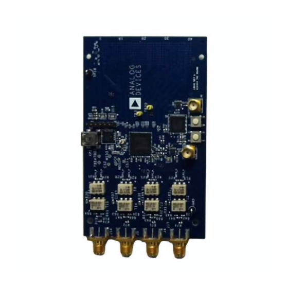
Figure 1. Block diagram of the FMC-EBZ lab Figure 2. Top and Bottom view of AD9144-FMC-EBZ bench set-up A low phase noise high frequency clock source should be connected to the SMA connector J1. A spectrum analyzer should be connected to the SMA connector J4. J5, J14 and J17 of the EVB should be connected to an oscilloscope. - Page 4 2. Plug the AD9144-FMC-EBZ into port FMC_1 of the ADS7 System. Use a USB cable to connect the EVB to your PC and connect the lab equipment to the EVB as shown in Figure 1. 3. Connect the ADS7 unit to your PC via USB and turn on the ADS7.
- Page 5 Figure 3. Initial DPG Downloader Panel Single Tone Demo Hardware and Software Start Up Procedure: 1. Run DPG Downloader. It will say AD9144 as shown in Figure 3 2. Execute Port Configuration ‘Below 7.5Gbps’. This will turn on the ADS7 FMC power supplies that power the FMC EVB.
- Page 6 Figure 4. DPG Downloader Display Step 2 3. Open SPIPro. It will say AD9144-FMC-EBZ in the upper left hand corner. 4. Select single link, JESD mode 0, Interpolation 2. Press ‘Configure DAC and Clock’ button. JESD204B PLL lock will turn green.
- Page 7 Figure 5. Fully Configured SPIPro Display 5. Select Single Tone under the Add Generated Waveforms Tab. Set Data Rate: 750Mhz, Desired Frequency: 112Mhz, Amplitude: -1dbFS, Uncheck Unsigned Data, Check Generate Complex Data (I and Q) 6. Populate the data playback selections as shown in Figure 6. 7.
- Page 8 Figure 6. AD9144-FMC-EBZ Fully Configured DPG Downloader Display 8. Here’s what you will see on DAC0, DAC1, and DAC3 on the scope Rev 29 Sep 2014 22:29 | Page 8...
- Page 9 Figure 7. DAC Outputs Scope Display 9. Here is what you will see at the output of DAC2 on the Spectrum Analyzer. Rev 29 Sep 2014 22:29 | Page 9...
- Page 10 Figure 8. DAC Output Spectrum Analyzer Display © Analog Devices, Inc. All rights reserved. Trademarks and registered trademarks are the property of their respective owners. www.analog.com Rev 29 Sep 2014 22:29 | Page 10...
Need help?
Do you have a question about the AD9144-FMC-EBZ and is the answer not in the manual?
Questions and answers