
Subscribe to Our Youtube Channel
Related Manuals for Thermo Scientific MaxQ Mini 4450


Summary of Contents for Thermo Scientific MaxQ Mini 4450
- Page 1 MaxQ Mini 4450 Shaker MODEL NO. SHKA4450, SHKA4450CC SHKA4450-1CE, SHKA4450CC-1CE SHKE4450, SHKE4450CC SHKE4450-1CE, SHKE4450CC-1CE 057-810-00 • 2/5/07...
-
Page 2: Table Of Contents
Table of Contents Safety Information ..............................3 Alert Signals ..............................3 Warnings ..............................3 Product Profile ..............................4 Analog Control Panel Features ........................6 Digital Control Panel Features ........................7 General Specifications ............................8 Unit’s Environmental Operating Conditions....................10 Unpacking and Installation ..........................11 Shipping Carton ............................11 Unpacking ..............................11 Location ..............................11 Electrical Requirements ..........................12 Platform Installation ............................13... -
Page 3: Safety Information
Safety Information Your Thermo Scientific MaxQ Mini 4450 Shakers have Alert Signals been designed with function, reliability, and safety in mind. It is your responsibility to install it in conformance with local electrical codes. For safe operation, please pay Warning attention to the alert signals throughout the manual. -
Page 4: Product Profile
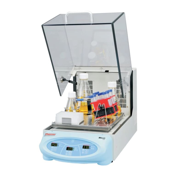
Product Profile The Thermo Scientific MaxQ Mini 4450 bench top, incu- bated shakers are available in either analog or digital con- trol configurations: • Analog shakers: SHKA4450, SHKA4450CC, SHKA44500-1CE and SHKA4450CC-1CE: con- trol temperature by a Proportional/ Integral/ Derivative microprocessor-based controller. - Page 5 RODUCT ROFILE • 6 permanently lubricated ball bearings. • 35 lb (15.9 kg) platform load capacity at safe speeds less than 400 rpm for analog shakers and less than 500 rpm for digital shakers. • UL, cUL and CE certification.
-
Page 6: Analog Control Panel Features
RODUCT ROFILE Analog Control Panel Features 1. SPEED Control: Sets platform rotation speed. 2. HIGH-LIMIT Light: Illuminates when high limit thermostat is controlling temperature. 3. TEMPERATURE Controller: Maintains temperature. 4. TIME(R): Allows user to choose continuous timing or set timed operation. 5. -
Page 7: Digital Control Panel Features
RODUCT ROFILE Digital Control Panel Features 15-18 23-24 21 22 19-20 10 11-12 1. SPEED Display: 3-digit LED indicates actual or set point speed 2. Up Arrow Switch: Increases platform rotation speed 3. Down Arrow Switch: Decreases platform rotation speed 4. -
Page 8: General Specifications
General Specifications Catalog Number SHKA4450 SHKA4450-1CE SHKE4450 SHKE4450-1CE SHKA4450CC SHKA4450CC-1CE SHKE4450CC SHKE4450CC-1CE Electrical Voltage AC 220-240 220-240 Amperage 2.25 2.25 Wattage Frequency Speed Accuracy 40 to 400 rpm 40 to 400 rpm 15 to 500 rpm ±1 rpm 15 to 500 rpm ±1 rpm Continuous or timed Continuous or timed Continuous or timed... - Page 9 ENERAL PECIFICATIONS Catalog Number SHKA4450 SHKA4450-1CE SHKE4450 SHKE4450-1CE SHKA4450CC SHKA4450CC-1CE SHKE4450CC SHKE4450CC-1CE Audible with flashing Audible with flashing Alarm Speed None None led indicate when led indicate when speed deviates more speed deviates more than 10% of set point than 10% of set point When speed When speed Speed Shut Off...
-
Page 10: Unit's Environmental Operating Conditions
ENERAL PECIFICATIONS Catalog Number SHKA4450 SHKA4450-1CE SHKE4450 SHKE4450-1CE SHKA4450CC SHKA4450CC-1CE SHKE4450CC SHKE4450CC-1CE Monitor speed, tem- Monitor speed, tem- RS232 Interface* None None perature and time perature and time with a computer with a computer Recorder Output* 10 mv/C output mon- 10 mv/C output mon- (Located on left side None... -
Page 11: Unpacking And Installation
Use the packing list below when unpacking to verify that the complete unit has been received. Do not discard packing materials until all is accounted for. The following items are included in the shipment: MaxQ Mini 4450 Shaker Operation Manual Registration Card Inspection Tag... -
Page 12: Electrical Requirements
NPACKING AND NSTALLATION • Allow approximately 2" (5 cm) of clearance around the unit for free air convection, accesso- ry attachments and user convenience. Electrical Requirements • SHKA4450, SHKA4450CC, SHKE4450 and SHKE4450CC shakers require a 120 VAC, 60 Hz power source. They are supplied with a 3- wire line cord and should be plugged into an outlet designed for 3-prong plugs. -
Page 13: Platform Installation
NPACKING AND NSTALLATION Platform Installation Select the appropriate platform for the vessels to be Caution shaken. A wide variety of platforms and accessories Do not operate shaker with an are available: unbalanced load. Platforms should be loaded for optimum stability. Do •... -
Page 14: Test Tube Rack Installation
NPACKING AND NSTALLATION Test Tube Rack Installation Position the test tube rack on the combination platform so that the cutouts on the rack's out- side bottom are aligned with corresponding mounting holes on the platform. There are two cutouts on each side of the rack. Secure the rack to the platform with mounting screws provided with the rack. -
Page 15: Operation
Operation Analog Please refer to page 6 for control panel reference. Warning It is recommended that shaking action be started at a low speed in Power Switch order to check that all vessels are Depress top portion of power switch to turn on secure and that no spilling of con- shaker. -
Page 16: Temperature Calibration
PERATION blank out for 2 seconds before showing the chamber temperature. Chamber or Setpoint Temperature Heat Indicator HEAT ON INDICATOR: The HEAT ON indicator lamp is lit when the chamber heaters are receiv- ing power. The lamp will normally flash when the chamber temperature is at set point. - Page 17 PERATION Allow the unit to run for at least 30 minutes. The controller display should now be indicating the set point temperature. Make note of the thermometer reading. Press and hold both arrow keys until the con- troller display indicates “tunE”. Release the arrow keys.
-
Page 18: Setting Hi-Limit Control
PERATION Setting Hi-Limit Control Please refer to page 6 for control panel reference. Make appropriate power connection. Turn power switch ON. Using a small screwdriver, rotate high-limit con- trol fully clockwise. Note Set chamber temperature. The hi-limit control is located on the right front side of the cabinet. -
Page 19: Setting Shaking Speed
PERATION Setting Shaking Speed Hold down appropriate arrow membrane switch Note in the speed module of the control panel, up or Speed can be changed without press- down, until desired speed is set up to 500 rpm. ing the START or STOP membrane SET RPM light will illuminate. -
Page 20: Setting Hi-Limit Control
PERATION Press and hold down arrow key to decrease temperature, release key when desired set point Note is obtained. The hi-limit control is located on the lower front side of the cabinet. Once set, temperature control is initiated by pressing the heat on button; the heater will react and start increasing the temperature to reach the set point. -
Page 21: Temperature Calibration
PERATION it will resume operation at the speed and timer settings that were entered at the time that AC power failed. Temperature Calibration Fill a 250-ml Erlenmeyer flask with approximate- ly 100 ml of water and position it at the approxi- mate geometric center of the shaking platform. -
Page 22: Setting Timer For Timed Shaking
PERATION Setting Timer for Timed Shaking Press TIMER/ELAPSED membrane switch until TIMER and SET TIME lights are illuminated. The HOURS or MINUTES light will also light up at this point depending on which option was previously chosen. Press HOURS/MINUTES membrane switch for desired timing mode. -
Page 23: Setting Timer For Continuous Timing
PERATION Setting Timer for Continuous Timing Press TIMER/ELAPSED membrane switch until TIMER light is off. The HOURS or MINUTES light will also light up at this point depending on which option was previously chosen. Press HOURS/MINUTES membrane switch for desired timing mode. Press START to begin timed shaking. - Page 24 PERATION selected under "Connect Using." Click "OK." 5. In the "COM1 Properties" box \ "Port Settings" folder select the following options: Bits per second: ∂ 19200 · Data bits: ∂ 8 · Parity: ∂ None · Stop bits: ∂ 1 ·...
-
Page 25: Using The Optional Cooling
PERATION Using the Optional Cooling Coil Either tap water or other user-supplied media from a refrigerated circulator flows through the submerged cool- ing coil. Adjust setpoint to the desired temperature. Connect the coolant hoses to the cooling coil fit- tings on the back of the unit. Start the coolant flowing through the cooling coil;... -
Page 26: Troubleshooting
Troubleshooting The following is intended as a reference guide to help in servicing this unit if problems should occur. Problem Possible Causes Solutions Shaker doesn’t operate Check if power cord is plugged in. Plug in. Check if power supply matches Locate power supply that matches requirements on data label. -
Page 27: Over Temperature Protection
ROUBLESHOOTING Over Temperature Protection In the unlikely event that the programmed hi-limit and the user adjustable hi-limit thermostats fail, there is a third over temperature thermostat. The thermostat is located underneath the shaker's back panel. If the shaker fails to heat with the "HEAT ON"... -
Page 28: Maintenance
Make no attempt to service or repair Wash the exterior of the unit with a soft cloth using a solu- a Thermo Scientific product under tion of mild soap and water, rinse off with clean water and warranty before consulting your dry thoroughly. -
Page 29: Replacement Parts
Replacement Parts PART NO. DESCRIPTION SHKA4450 SHKE4450 SHKA4450-1CE SHKE4450-1CE 057-810-00 Operation Manual 150-318-00 Belt, Drive 150-288-00 Belt, Drive 3/16 X 22-3/8 160-208-00 Chamber Blower-120V 330-399-00 Circuit Breaker, 0.8-Amp 330-119-00 Circuit Breaker, 10-Amp 485-360-17 Controller, Programmed 720-592-01 Cover 420-265-01 Dust Cover, D-Sub 790-078-00 Mounting Feet 560-281-00... - Page 30 EPLACEMENT ARTS PART NO. DESCRIPTION SHKA4450 SHKE4450 SHKA4450-1CE SHKE4450-1CE 830-476-00 Spring, Gas 440-080-00 Switch, Push Button-Cover 440-397-00 Switch, Mini Rocker-Heat 440-359-00 Switch, Rocker 660-111-00 Tachometer 410-632-00 Temp Sensor, RTD 920-301-00 Thermostat 330-400-00 Thermostat, OTP 270-135-00 Timer 229-395-00 Wiring Diagram 229-392-00 Wiring Diagram 160-209-00 Cooling Fan-240V...
-
Page 31: Ordering Procedures
Ordering Procedures Please refer to the Specification Plate for the complete model number, serial number, and series number when requesting service, replacement parts or in any corre- spondence concerning this unit. All parts listed herein may be ordered from the Thermo Scientific dealer from whom you purchased this unit or can be obtained promptly from the factory. -
Page 32: Warranty
Warranty This Thermo Scientific product carries a five year warranty on parts, one year warranty on labor and a lifetime warranty on the drive mechanism. The warranty is effective from the first to occur (i) the date the product is sold by the manufacturer or (ii) the date the product is purchased by the original retail customer (the “Commencement Date”).
Need help?
Do you have a question about the MaxQ Mini 4450 and is the answer not in the manual?
Questions and answers